Tham said:Thanks Iko. Will set at 2.5A and hope it will not be hotter. Will Q1/Q2 dissipate same heat as v1?
Neither the pnp nor the npn will dissipate much power, no concern there. The mosfets will dissipate just as much power as v1 if you set it up for the same current and voltage. Don't forget the output cap, and watch out of oscillation (if you don't have a scope, you will notice a lower output voltage if the reg oscillates).
An Update:-
Tested with a 90ohm power resistor at the output and it measures 12.54V. Plug it the T amp and adjust for 250mV for 2.5A current and it measures 12.54V at the output too. Played some music and no distortion heard. The sink heats up pretty fast and after a couple of minutes is as hot as the v1 built.
Soundwise, it seems to add some vibrancy to the overall presentation with improved transparency. It is yet to run in so it may sound different later but I think I am hearing the same characteristics between v1 and v2 low current shunts.
Hope it will remain stable in the long run.
Good news. Maybe you can elevate the sink off the floor by two makeshift ''feet'' so the air can circulate better through its fins.
P.S. Can you point to the post number of the exact schematic you use? Try to listen to both versions with exactly the same output capacitor value and brand at a point. So to know what part of the differences can be attributed there if any. Also are the nodes between the two builds the same? I.e. do you use remote sensing in one of them or both, and is your grounding scheme comparable?
P.S. Can you point to the post number of the exact schematic you use? Try to listen to both versions with exactly the same output capacitor value and brand at a point. So to know what part of the differences can be attributed there if any. Also are the nodes between the two builds the same? I.e. do you use remote sensing in one of them or both, and is your grounding scheme comparable?
Salas said:They talk about the shunt current sensing resistor, not the CCS setting one I guess.


There is a 0.1R under the shunt Mosfet in V1.5 so to measure the shunted current because in its CCS they use a Vgs setting trimmer / resistor without one in line with the main current route so to directly measure its drop across and derive the total current as in V1 or other versions. With a T-amp that has next to nothing constant draw, seeing 250mV on it is a good approximation so to evaluate the total current setting as 2.5A. But with another circuit that has enough steady draw, the shunt current sensing on the 0.1R does not tell the whole story. ICCS=ShuntedCurrent+LoadCurrent.
Tham said:
Hope it will remain stable in the long run.
Nicely done Tham, enjoy! BTW, there is no reason why it should not be stable with the time. I'd say keep an eye on the heat. You might need to use a quiet fan; they make very silent fans for computer cases (I know because a friend could not stand the noise of the computer and replaced the fans with some ultra silent ones). You might benefit also from very short distances (I see some long wires on the mosfets; hope your connection to the t-amp is much shorter). I would use very short non-stranded copper to connect to the next stage, the t-amp.
Andrew, you're right though, it would have been a bit of a challenge to set the desired current with R values in the 0.1 range. It's one of the reasons to use this different biasing mechanism.
Hi Salas,
Already raised the heatsink about an inch and also applied new heatsink compound.
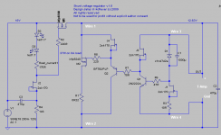
v1 was base on post #825 and v1.5 on post #857 schematics. V1 has 2x1000uF ZL output cap while v1.5 has an Elna RE3 470uF output cap. I try to follow the schematic as close as possible but not sure of the nodes, grounding, etc. Probably posting a picture of the underside of the two builts may help.
Already raised the heatsink about an inch and also applied new heatsink compound.
v1 was base on post #825 and v1.5 on post #857 schematics. V1 has 2x1000uF ZL output cap while v1.5 has an Elna RE3 470uF output cap. I try to follow the schematic as close as possible but not sure of the nodes, grounding, etc. Probably posting a picture of the underside of the two builts may help.
Iko, I mounted the mosfets on the heatsink and linked them to the shunt with wires so that I can easily compare v1 and v1.5. The final arrangement would have the mosfets mounted on the pcb and fixed directly onto the heatsink.
Will watch out for the heat and may have to use a fan or change to a bigger heatsink.
Will watch out for the heat and may have to use a fan or change to a bigger heatsink.
Post 857 schematic has nodes arranged for remote sensing capability. I.e. You can use 4 wires to the load. 2 for sensing the main wire's impedance, and the main wires themselves. The same can be done with V1. You use 2 wires for now on both I suppose. Remote sensing significantly avoids the supply wire to mess with the reg's output impedance. Some like the subjective effect, others not. Depends on how long and thick was the simple cable arrangement and synergistic or not equipment's character. OK good job. Congrats. Let it burn in. At a point just put its output cap on V1 so to compare directly.
Attachments
the remote sensing that Salas refers to is the way to design the PCB.
We have not looked at stability of true remote sensing using longer wires to the load. These will include additional parasitics and may not sound right due to oscillation at worst and peaking of fast signals at best.
We have not looked at stability of true remote sensing using longer wires to the load. These will include additional parasitics and may not sound right due to oscillation at worst and peaking of fast signals at best.
I congratulate Tham for having the hottest most inefficient class-d t-amp in the world 

Reminds me of the saying that "you give with one hand, and take with the other"
But worry not, I already have an idea for a simple pic controller based automatic shunt current adjustment that will be more efficient. Would anybody be interested in something like that? Very simplistic
The reality is that we don't need to pass so much current most of the time, since we're not listening so loud continuously.


- Status
- This old topic is closed. If you want to reopen this topic, contact a moderator using the "Report Post" button.
- Home
- Amplifiers
- Power Supplies
- The simplistic Salas low voltage shunt regulator