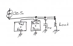
no, your diagram has only corrected the top of the measuring bridge.Salas said:Like this more or less? (All grounds to a star I would prefer).
salas, I would treat both points of the "Vref+Req" module as sense points. Then their traces should be connected to the load and load ground points respectively, no? The load ground can go to star point. I've done some simulations of small resistance in the traces and it agrees.
Edit: Andrew, thanks for pointing it out.
Edit: Andrew, thanks for pointing it out.
yes, now just flip over the whole central section to show everything in it's correct position (well almost).ikoflexer said:have another look at post 857. Is this more like it?
....................... many people see the schematic and automatically think that also shows the layout/connection points, which may often not be the case.
")
I would show C2 connected at the top and bottom corners. Otherwise some will think it is important for the sense points to be connected to the cap.
It is important that the sense points are connected to the output terminals.
The location of the cap is much less critical.
However, Salas' comment on star connecting is very valid. Just identify the priorities since not everything can connect perfectly to the star. Some connections have to compromise.
IMHO, a proper layout should be done and the schematic used only as an rough indication of what the layout should be. I guess what I'm saying is that a proper discussion on the PCB layout should be done with a layout in hand, i.e. traces and all that.
Otherwise, I would advise whoever wants to implement the schematic to at least keep the two wires connecting the regulator and the load as short as possible, and the same length (seriously thick too).
Otherwise, I would advise whoever wants to implement the schematic to at least keep the two wires connecting the regulator and the load as short as possible, and the same length (seriously thick too).
Salas said:It is best for the CCS to be connected with shortest wire to the load too? I.e. Schematically moved to the right?
the CCS mimics a very high impedance.
If the lines from it to the load or to the sense points are longer then these lines will have a bit of added inductance.
Any additional impedance from the voltage source to the shunt element improves the attenuation of the unwanted pulses/glitches.
But, stability must be maintained.
Here is where plugging in parasitics to the model and asking the simulator the right questions is paramount to understanding what the overall regulator is doing.
some of our Members are very good at turning a schematic proposal into a PCB layout.ikoflexer said:IMHO, a proper layout should be done and the schematic used only as an rough indication of what the layout should be.
Many have volunteered to do this job for us and we are grateful.
However, those same volunteers do not always realise just what the schematic is hiding as the untold message.
We should help them whenever we can by placing components in the correct locations, provided it does not add to the complexity of the schematic and provided that practice does not break the normal schematic rules.
Usually it is the circuit designer who knows what each component or circuit does and who also knows where it can do it's job best.
Hi,
I was on for 40 or so of the Cetoole until we discovered it did not perform as the model predicted.
I have followed this thread and others to find a suitable replacement for the Cetoole.
If we get this Salas version right AND it performs up to spec then I am certainly in for many cheap PCBs.
What made Cetoole attractive to the extent of 1500 or so PCBs was it was very small and very cheap. There were 4projects on each PCB.
If we can do the same squeezing with this regulator then someone is going to be running a very big Group buy.
i have deliberately tried to reduce my input on this thread, since Salas and others have already heard how good it can be.
But I think we are very close to a group of final versions that can be universal and thus popular. But all the versions must fit the same small PCB.
Please don't go the route of integrated shunt and buffer and muting and switching and .. and... and. Please don't.
Hi Tham, yes, if you feel brave, that's the version I'd say works best so far (in my simulations). Seems to have no problems stability wise, etc. Of course, you would be the first to build it, so you'd be the first to know how it would be in reality. As salas said, if it doesn't work well, you can always just remove the parts and have v1.
Edit: of course, which ever version you go for, I'll be around if you need help. Let us know.
Edit: of course, which ever version you go for, I'll be around if you need help. Let us know.
- Status
- This old topic is closed. If you want to reopen this topic, contact a moderator using the "Report Post" button.
- Home
- Amplifiers
- Power Supplies
- The simplistic Salas low voltage shunt regulator