")
salas your reply on the other thread im copying here for discussion
>>
Vrset=Vgs-Vf(3leds). Stays constant depending on the Vgs curve set point. If Vrset changes with input voltage then something is not working right in the CCS. The shunt part 5 Leds Vref is about 10V not 12V. If 12V maybe something is wrong there.
>>
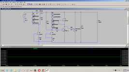
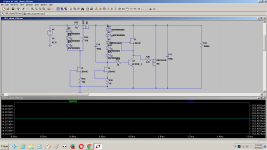
A quick sim in the LTspice you can see the current through the CSS resistor. Why is this happening?
>>
Vrset=Vgs-Vf(3leds). Stays constant depending on the Vgs curve set point. If Vrset changes with input voltage then something is not working right in the CCS. The shunt part 5 Leds Vref is about 10V not 12V. If 12V maybe something is wrong there.
>>
A quick sim in the LTspice you can see the current through the CSS resistor. Why is this happening?
Attachments
Huge thread and I'm struggling to find the info I need....
1. If I want 12v out (+ve and -ve rails) will a 2 x 15v 50vac transformer power both rails?
2. For the -ve rail are this and this the correct items?
3. The guide mentions C102, 104, 202 and 204 with a range from 4.7 to 10uf. Is this for the standard and hot rod versions (eg 4.7uf for the standard)?
1. If I want 12v out (+ve and -ve rails) will a 2 x 15v 50vac transformer power both rails?
2. For the -ve rail are this and this the correct items?
3. The guide mentions C102, 104, 202 and 204 with a range from 4.7 to 10uf. Is this for the standard and hot rod versions (eg 4.7uf for the standard)?
A 50VA 15-0-15Vac transformer will allow a maximum continuous DC output of ~820mAdc.
For cool operaton load it to ~50% of that maximum rating, i.e. <=410mAdc per supply rail.
A 15-0-15Vac gives ~ ±22Vdc on the UK mains supply, but this varies during the day. The lowest you are ever likely to see is ~85% of that i.e. ±18.7Vdc
That is ~6.7V of drop across the CCS for an output of 12Vdc
Your transformer should work for all UK voltages in the range 216Vac to 253Vac.
12Vac does not work for a 10V output.
It's the CCS that needs volts drop to work properly.
15Vac was adopted to make sure the DCB1 on 10V worked for the usual range of mains voltage.
It turns out that 15Vac also allows 12V output for a normal range of mains voltage.
I would suggest that 12VA 15-0-15Vac is the absolute minimum requirement for ±12Vdc @ 100mAdc using the Salas Style Shunt regualtor.
Last edited:
salas your reply on the other thread im copying here for discussion
>>
Vrset=Vgs-Vf(3leds). Stays constant depending on the Vgs curve set point. If Vrset changes with input voltage then something is not working right in the CCS. The shunt part 5 Leds Vref is about 10V not 12V. If 12V maybe something is wrong there.
>>
A quick sim in the LTspice you can see the current through the CSS resistor. Why is this happening?
As Andrew said already you need to exceed the recommended minimum Vin-Vout first so the CCS will stabilize. After that point there will be controlled voltage drop differences across the setting resistor possible values due to the Vgs curve vs Id as seen in any particular MOSFET's manual and little ones due to VDS and rising thermals. In your example the first input voltage is insufficient, that is why you see a marked difference when applying that second still short but more appropriate input voltage.
hi,
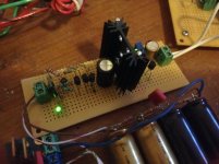
i would like to share my experience concerning a CCS setup i found particurlarly good in a Salas reg that is powering a DAC analog side, but it should also be suitable for any low current applications , whithin power and voltage specs, of course.
it is not has quite the "drive" of the irfp240 cascode soundwise, but if you don't need a lot of current, i found paralleling bc550c to give the "most for my money". The highs sounding more realistic and defined could be a an appropriate description of the benefit.
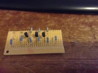
First, i tried paralleling six on a "card"(see picture), but it just wouldn't work because of oscillations.
The i placed 1 then 2 and now 3 in parallel on a tighter layout and it works fine up to now...
Bc849 a/b/c (or mmbt4401, which i plan to try) is pretty much recommended for Q3 because they perform better at lower Vce.
It is questionnable whether to-92 devices can take some wattage, so not to be forced to parallel too much devices, but if you want to push them, i had a good experience with glueing them with epoxy inside a standoff ( see picture). I would say that way they can withstand 1W attached to a bigger sink. If you sand-off the back of the t0-92 device plastic to make it look like a rectangle and epoxy it in a rectangle shaped hole that will minimize the distance between the die and the heatsink metal, than i would say maybe 1.5W can be applied safely (YMMV).
Also, 2n5457 gave me better better "drive", but sound a tad bit more noisier, so i keep them for when noise is not an absolute necessity in my setup. Right now i'm waiting for some 2sk246 to test also.
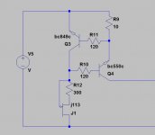
edit: shown is a negative ccs, which requires a transformer of it's own to work ( reverse reg). I have not tried a positive version, but it is possible that pnp bjt's will perform a tad bit worse.
edit 2: voltage source is reversed in the attached schematic!
i would like to share my experience concerning a CCS setup i found particurlarly good in a Salas reg that is powering a DAC analog side, but it should also be suitable for any low current applications , whithin power and voltage specs, of course.
it is not has quite the "drive" of the irfp240 cascode soundwise, but if you don't need a lot of current, i found paralleling bc550c to give the "most for my money". The highs sounding more realistic and defined could be a an appropriate description of the benefit.
First, i tried paralleling six on a "card"(see picture), but it just wouldn't work because of oscillations.
The i placed 1 then 2 and now 3 in parallel on a tighter layout and it works fine up to now...
Bc849 a/b/c (or mmbt4401, which i plan to try) is pretty much recommended for Q3 because they perform better at lower Vce.
It is questionnable whether to-92 devices can take some wattage, so not to be forced to parallel too much devices, but if you want to push them, i had a good experience with glueing them with epoxy inside a standoff ( see picture). I would say that way they can withstand 1W attached to a bigger sink. If you sand-off the back of the t0-92 device plastic to make it look like a rectangle and epoxy it in a rectangle shaped hole that will minimize the distance between the die and the heatsink metal, than i would say maybe 1.5W can be applied safely (YMMV).
Also, 2n5457 gave me better better "drive", but sound a tad bit more noisier, so i keep them for when noise is not an absolute necessity in my setup. Right now i'm waiting for some 2sk246 to test also.
edit: shown is a negative ccs, which requires a transformer of it's own to work ( reverse reg). I have not tried a positive version, but it is possible that pnp bjt's will perform a tad bit worse.
edit 2: voltage source is reversed in the attached schematic!
Attachments

Last edited:
- Status
- This old topic is closed. If you want to reopen this topic, contact a moderator using the "Report Post" button.
- Home
- Amplifiers
- Power Supplies
- The simplistic Salas low voltage shunt regulator