Its an old big thread, what can you do. Use M1 IRF9610 M2 1RF9530 C2 1000uF and hot-rod CCS setting (ref 1st schematic you attached) if you are to practically make an example. Good luck.Thanks Salas. Should've started reading from the end of the thread")
Okay, here's the plan for the "Salas C4S Dual", aka. CCCCS, with 'Cross Coupled Constant Current Sources' !
I didn't include any bipolar CCS to 'keep it Salas', but I swapped the expensive 2SK170 (which is 1.50 apiece at my favourite supplier) for the about equally current-matched BF256B (which is only 0.15 apiece...). And I increased the JFET-resistor in the hot rod part to 1k, so that the little JFET doesn't "hot rod" and shares his voltage about equal with the resistor.
Once I've laid out a proper layout, I'll build a prototype and test it out with my Ulti-Preamp. I hope to get this done before I can start building my new house; I'll report back in any case though, even if it takes a year or more to complete.
!I didn't include any bipolar CCS to 'keep it Salas', but I swapped the expensive 2SK170 (which is 1.50 apiece at my favourite supplier) for the about equally current-matched BF256B (which is only 0.15 apiece...). And I increased the JFET-resistor in the hot rod part to 1k, so that the little JFET doesn't "hot rod" and shares his voltage about equal with the resistor.
Once I've laid out a proper layout, I'll build a prototype and test it out with my Ulti-Preamp. I hope to get this done before I can start building my new house; I'll report back in any case though, even if it takes a year or more to complete
.Attachments
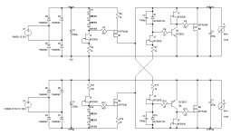
Looks sound, but you might want to do worst-case simulations for power up and power down to verify that you are not exceeding base-emitter reverse breakdown voltages on Q2 and Q4. Or, you could just include 1N4148s across the B-E junctions to clamp any such transients.Okay, here's the plan for the "Salas C4S Dual", aka. CCCCS, with 'Cross Coupled Constant Current Sources'
I didn't include any bipolar CCS to 'keep it Salas', but I swapped the expensive 2SK170 (which is 1.50 apiece at my favourite supplier) for the about equally current-matched BF256B (which is only 0.15 apiece...). And I increased the JFET-resistor in the hot rod part to 1k, so that the little JFET doesn't "hot rod" and shares his voltage about equal with the resistor.
Once I've laid out a proper layout, I'll build a prototype and test it out with my Ulti-Preamp. I hope to get this done before I can start building my new house; I'll report back in any case though, even if it takes a year or more to complete
Substitutions usually work straight away in this topology. Since the VDS problem for higher Vp JFETs is hopefully taken care off in the dual, there should be an optimum regarding the base resistor & terminal cap values also. It's easy enough I take a look in the open loop analysis. Are you surely going to use the TO-247s? The types matter in optimization.
Looks sound, but you might want to do worst-case simulations for power up and power down to verify that you are not exceeding base-emitter reverse breakdown voltages on Q2 and Q4. Or, you could just include 1N4148s across the B-E junctions to clamp any such transients.
EDIT: Doesn't look good at switch-off, breakdown voltage of BC550 is 5V only, no? I'll add clamp diodes. Thanks for pointing that out!
Are you surely going to use the TO-247s? The types matter in optimization.
Shouldn't I? From what I've read so far they seem to be your preference. The abovementioned TO-220's would save some board space, but I'm a fan of beefy devices...
Attachments
Last edited:
Those examples in the start of the thread have the big ones since I could heavily hot-rod them for circuits like the DCB1 and the older phono. Heavy hot-rod brings down Zo and THD. Those devices were subjectively complimentary to the sonic traits of those client circuits. Also practical to mount and isolate, tough guys. Later on I had also used enough different types that I was evaluating along the various client circuits. Anyway I will have a look in your particular JFET devices mix open loop traits in combination with the borrowed parts values when having some time later on. Mainly about verifying the phase margin & in-band flatness are still in check.
I gave it a look. For your parts combination I suggest R4 & R18 = 10R. C2 & C7 = 33uF. See to have healthy current through the LEDS (say 5mA) and CCS current set to double your load's peak to peak current swing when sine wave driven just before clipping, not just thinking in terms of its idle bias. The TO-247s yet again responded nicely in this particular parts and values configuration analysis.
Thanks again, Salas. Idle current (measured) is 68mA for each rail, maximum current is almost 180mA (simulated) with 16R load, which it won't see actually, since I'm not going to use it as a headphone amp. The CCS with 10R will barely reach those 180mA, which is about double of what I need if I don't go lower than 600R load.
Final case and heatsink will tell if I can double up on that and be on the safe side. Depends on how much cooling I can stuff into 1U without needing a fan...
Final case and heatsink will tell if I can double up on that and be on the safe side. Depends on how much cooling I can stuff into 1U without needing a fan...
Its not only safer when having the heat exchange luxury, it also increases the proportion of static current to dynamic current thus less mini-modulation % THD goes on by the load on the rails. Use the chassis floor as sink. Also keep in mind that Vout is Vz + whatever potential to ground it sits on. Let us know more whenever you finish. Good luck.
P.S. I hope those general purpose VHF/UHF BF256Bs are relatively low noise also beyond being fast.
P.S. I hope those general purpose VHF/UHF BF256Bs are relatively low noise also beyond being fast.
Process 50, one of the go-to chips for low input and feedback capacitance. How well they are being made today I don't know, but in the good old days the TI parts were doing about 3nV/sq rt Hz around 1kHz and at healthy currents.P.S. I hope those general purpose VHF/UHF BF256Bs are relatively low noise also beyond being fast.
BF862 are higher C and lower breakdown voltage, but considerably better performance in terms of noise. Unfortunately only in surface mount.
I have 50-100 of those on a cut tape. I also got a measurement socket. They are high IDSS like average V Toshiba but with more slant saturation region curves than Toshiba. Since few mW because SMT they better be controlled with source degeneration resistor when carrying some potent enough voltage across. That will up their noise. If really 3nV the 256s will do acceptably.Process 50, one of the go-to chips for low input and feedback capacitance. How well they are being made today I don't know, but in the good old days the TI parts were doing about 3nV/sq rt Hz around 1kHz and at healthy currents.
BF862 are higher C and lower breakdown voltage, but considerably better performance in terms of noise. Unfortunately only in surface mount.
They (862) have very low pinchoff, so not all that suitable with source ballasting. Danyuk did some measurements of them and others for voltage noise (it was in some note for EDN or ED) and the 862 was a winner for amplifiers.I have 50-100 of those on a cut tape. I also got a measurement socket. They are high IDSS like average V Toshiba but with more slant saturation region curves than Toshiba. Since few mW because SMT they better be controlled with source degeneration resistor when carrying some potent enough voltage across. That will up their noise. If really 3nV the 256s will do acceptably.
It would be nice if Toshiba still made the 2SK246, which had a longer channel and could be temperature-compensated with external source resistances for high Z current sources.
For reasonable voltages I cascode the 862 with parts like the J111. A really high performance combination.
P.S. I hope those general purpose VHF/UHF BF256Bs are relatively low noise also beyond being fast.
Naah, come on
! Now it urges me to get some 2SK170's too, just for the sake of testing the difference. But then again, when I have the SK's, what do I need the BF's for then? 
Okay, count me in
 . That's what I've built a measurement preamp for anyway... Anybody willing to donate me some 2SK170's?
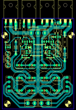
 This is what my prototype board might look like.
It's 80x100mm and single layer only, for ease of replacing components. Maybe I'll add some sockets for the JFETs and remove them later to solder in the final components.
There're some jumpers to switch between opposite rail reference and ground reference, in case something does not work as espected. Again the final choice may be soldered.
The big 5W resistor footprint was chosen to allow bigger resistors to run cooler. There's a smaller one in parallel, which could either be used solely or fitted later on for increased overall current.
I opted for several smaller filter caps, to keep the height down if needed. Low-profile snap-in's are available, but they're rather special, harder to obtain parts, so I excluded them beforehand.
The rectifiers are placed to the sides so that they might be bent over and bolted to the chassis - just in case.
2SK170 fit in the same space as the BF256B, they just need to be turned around by 180°, which makes replacement a charm and the layout almost universal.
The three inevitable bridges were chosen to double as convenient measurement points, although I plan to have made a naked prototype without the neat printing.
So if nobody finds any gross mistakes, I'll place an order in the course of next week.
It's 80x100mm and single layer only, for ease of replacing components
. Maybe I'll add some sockets for the JFETs and remove them later to solder in the final components.There're some jumpers to switch between opposite rail reference and ground reference, in case something does not work as espected. Again the final choice may be soldered.
The big 5W resistor footprint was chosen to allow bigger resistors to run cooler. There's a smaller one in parallel, which could either be used solely or fitted later on for increased overall current.
I opted for several smaller filter caps, to keep the height down if needed. Low-profile snap-in's are available, but they're rather special, harder to obtain parts, so I excluded them beforehand.
The rectifiers are placed to the sides so that they might be bent over and bolted to the chassis - just in case
.2SK170 fit in the same space as the BF256B, they just need to be turned around by 180°, which makes replacement a charm and the layout almost universal
.The three inevitable bridges were chosen to double as convenient measurement points, although I plan to have made a naked prototype without the neat printing.
So if nobody finds any gross mistakes, I'll place an order in the course of next week
.Attachments
170 and 256
They are both symmetrical devices for these purposes, so drain and source are interchangeable.
The pinout of the 170 has the gate in the middle. The pinout of the 256 has the gate on one end. A 180 won't accomplish the mapping.2SK170 fit in the same space as the BF256B, they just need to be turned around by 180°, which makes replacement a charm and the layout almost universal
They are both symmetrical devices for these purposes, so drain and source are interchangeable.
They (862) have very low pinchoff, so not all that suitable with source ballasting. Danyuk did some measurements of them and others for voltage noise (it was in some note for EDN or ED) and the 862 was a winner for amplifiers.
It would be nice if Toshiba still made the 2SK246, which had a longer channel and could be temperature-compensated with external source resistances for high Z current sources.
For reasonable voltages I cascode the 862 with parts like the J111. A really high performance combination.
I am sometimes using J111s for that purpose too. BF245B & C also. Source ballasting won't make the TC right because there is no usable cross temperature section in their curves. I only had in mind plain current limiting just for securing safe dissipation in highish VDS places. Because tiny and high IDSS at the same time.
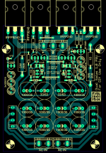
This is what my prototype board might look like.
Looks nicely arranged. You would want to mark + 0 - out and ~ ~ transfo input I guess. Also maybe print Customized Salas 1.0 PSU By Preamp - For DIY Use Only. Or something like that. There is space between right hand bridge and power resistor for some legend print.
- Status
- This old topic is closed. If you want to reopen this topic, contact a moderator using the "Report Post" button.
- Home
- Amplifiers
- Power Supplies
- The simplistic Salas low voltage shunt regulator