james, good to hear about the CT stuff. I'll have to try that. Could it be that it's responsible by itself for the black background you're experiencing?
Alright, the pcb, let's see, I have a few comments.
1. Considering that there are people that would only use the + version, perhaps it's best to have them separate.
3. Using a jfet instead of R10 improves very slightly the ripple rejection in simulation. However, it may not be audible; if the pcb had two holes on one side people can fit either a resistor, or the jfet. Easy thing to accommodate.
4. Did you notice the sharp dip at low frequency in the ripple rejection bode plot? C1 is responsible for that. There is a nasty phase thing there too. A small size resistor smooths it out. Again, we could simply omit it, or allow for it, and who doesn't want it just passes it over with a jumper? Up to you.
5. I could see no difference without it. salas, did it make a difference for you?
6. Is it necessary? Recommended?
IMHO, the fewer parts, the better. I would stick with choosing the right zener for the desired output voltage. A 50R resistor above the zener seems to slightly affect the output impedance, while raising the voltage by about 0.4V.
A word of caution on one part of the layout. The traces around M2 are very important. They should be as short as possible. The slightest inductance there decreases the output impedance by a lot.
jameshillj said:
1. One pcb for + and - rails?
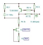
2. Using inverted 2skk170s rather than j74? or other devices, pinouts?
3. pads for a k170 option for R10?
4. extra Resistor as per your new Cct in series with C1 or is that a SIM thing?
5. Is there a Resistor between j1 source and 0v?
6. Is there to be a Resistor between the Shunt M2 and 0v?
I would like a small adjustment to the voltage - about 0.5 volts to compensate for zeners, correct for amp offset, etc, etc. Would a small pot (50R?) between zener and rail stuff up the performance?
Could you check this out with your magic circuit cruncher thing!!
Suggestions are MOST WELCOME - I'll start out with the extra tracking that we learned about with the Toole shunt layout and see what happens.
I'll get started into the pcb tomorrow (or today actually!)
For now ... Jh
Salas said:5 & 6. If its high quality high frequency and low esr, it helps. If not, better avoid. More interaction than filtering. Better with some passive pre filtering. No difference even in your sim with the cap or without it?
Sorry, salas, I don't know which cap and sim you're referring to?
jkeny said:Can somebody define the voltage & current operating range of this regulator?
It has been made from 13V to +/-46V. From 90mA to 3A, I know of regs in service. Also jwb made it at 9V.
mikelm said:Salas,
I have some irf530n's so if I buy some irf9530n's I will have enough for some dual supplies.
do you think these will sound ok or was irfp9240 your special choice ?
thx
mike
With 9610s I know it works faster. It will be more open in bandwidth with 530s too. The 9240 I know it will not oscillate with non careful layout, and it sounds OK. Hefty. You may make it with 530s and let us know. In general I don't go recommending bandwidth more than needed.
Salas said:100u bootstrap cap, top left, or left most.
It makes a big difference in the ripple rejection. I'll show you the plots later with and without. You're right, one can prefilter.
jkeny, the output voltage will be dependent on the zener used. The input voltage should be between 5 and 10 volts higher than the desired output; you need the voltage drop for good regulation.
Salas said:
I preferred the simple and widely available Zener solution. Somewhere I have read that it is even better, but I have not tested.
Its a finished project as much as I am concerned. Many people are very happy with it. But of course its up to you guys if you want to test it with more elegant additions or performance boosting twists.
I think you'd have to be crazy to use a zener above 6.3V. A red LED makes so much less noise, and adding noise sources together is sublinear, so you can add as many of them as you like. I use four red LEDs in my 9V version.
Zeners less than 6.8V are far more quiet than their high-voltage counterparts.
Has anyone (besides me) done a PCB layout of this regulator? My layout can be seen in this PDF but I'd love to see some others. In mine, I put the current source at the load point. I tried to sensibly use separate ground tracks where I felt the ground currents might interfere with one another.
'evening to all, just up on a lazy day!
Okay - we have lined up the horses and jockeys ...
1. +ve supply layout for now (not much difference anyway)
2. Hence - (been saving that one!) j1 = k170 only, j2 = room for oyjer pins later.
3. R10 <-> j3 plus options space
4. Include R with radial. axial C1 (and the HFZ size)
5. leave our extra R at j1 (maybe space?)
6. I like this 0.1R so can directly measure Shunt current - but as tracking here at M2 is critical, possibly add the extra surface mount on top of main track for optional cutting of ... I'll try it and see.
I see a mention of a "pre filter" input cap - perhaps a 1,000uF radial option? Plus the usual 5mm c/c terminal blocks? And perhaps to see if can squeeze in some closer pads for the IRF9610s without trouble - will use the usual offset pin scheme for power M1,2 - look a bit strange at first.
That about covers most everything, so I'll get started and see what it looks like - then we can get stuck into all the usual errors and mods. We've got the new Xmen movie on tonight - great brain food, but the usual ghastly sound!
jwb said:I think you'd have to be crazy to use a zener above 6.3V.
Naah, not that dramatic noise from a cap bypassed and locally ccs'd Zener. If it was so noisy it would hiss. Some who made it in the 15-25 of Volt, report they thought it was switched off when used on headphone amps. The 8.2V Zener value is said to be specifically noisier of all. Of course if someone wants to make a lengthy LED string for over 24V regs, it will look very cool, but I doubt if there will be some appreciable practical difference, since the leds will become enough by then.
jameshillj said:'evening to all, just up on a lazy day!
Okay - we have lined up the horses and jockeys ...
1. +ve supply layout for now (not much difference anyway)
2. Hence - (been saving that one!) j1 = k170 only, j2 = room for oyjer pins later.
3. R10 <-> j3 plus options space
4. Include R with radial. axial C1 (and the HFZ size)
5. leave our extra R at j1 (maybe space?)
6. I like this 0.1R so can directly measure Shunt current - but as tracking here at M2 is critical, possibly add the extra surface mount on top of main track for optional cutting of ... I'll try it and see.
I see a mention of a "pre filter" input cap - perhaps a 1,000uF radial option? Plus the usual 5mm c/c terminal blocks? And perhaps to see if can squeeze in some closer pads for the IRF9610s without trouble - will use the usual offset pin scheme for power M1,2 - look a bit strange at first.
That about covers most everything, so I'll get started and see what it looks like - then we can get stuck into all the usual errors and mods. We've got the new Xmen movie on tonight - great brain food, but the usual ghastly sound!
G'day!
")
Good luck! Waiting for news!
the "jwb masterpeice"
I just had to sneak a look at your "little pdf" over a cuppa, jwb, and there appeared this "masterpeice". " just knocked it up over a lunch break, eh!! Congratulations. That's is indeed a nice peice of work and a real example of a different approach. I think this is the same circuit as your post #283 - I'll print off this and put it beside your pcb - a rather different orientation with that CCS down the bottom as T55, C105, with T53 as the driver smd, etc, I see those 4 little surface mount leds across C97 on the RHS Reg tht you mentioned ....will print off the cct to follow the different orientation - a nice puzzle working it backwards - this must be what the China Copy House does all the time - it's a whole lot easier to copy than to actually design.
Incidently, noticed your raw supply R-C-R-C ripple reduction. I have given up on trying to get folks to try this - seems to have gone out of fashion or something - noticed Denis Moorecroft made a point about it on his DNM Audio site where he explains the T-Network caps.
Sorry about that - hit a wrong button or something strange.
I replaced the 8v2 zener in the headamp with 4 basic reds and a green to get about 8.2v also, and yes it was a lot quieter.
Must add that when I changed out the bipass cap, this also changed things a bit - nothing is ever just simple!
I replaced the 8v2 zener in the headamp with 4 basic reds and a green to get about 8.2v also, and yes it was a lot quieter.
Must add that when I changed out the bipass cap, this also changed things a bit - nothing is ever just simple!
jwb said:
I think you'd have to be crazy to use a zener above 6.3V. A red LED makes so much less noise, and adding noise sources together is sublinear, so you can add as many of them as you like. I use four red LEDs in my 9V version.
Zeners less than 6.8V are far more quiet than their high-voltage counterparts.
Has anyone (besides me) done a PCB layout of this regulator? My layout can be seen in this PDF but I'd love to see some others. In mine, I put the current source at the load point. I tried to sensibly use separate ground tracks where I felt the ground currents might interfere with one another.
This is not entirely correct, zeners can have as low noise as LED, in certain conditions even lower noise than LED. Zeners below approximately 6V have true zener breakdown and above this they have avalanche breakdown. The important distinction seems not to be which type of breakdown they exhibit, but how close to
from the transition they are. Zeners close to the transition are noisy as hell, between 6 volts and 7.5 volts being the worst. Low voltage zeners have moderate noise, higher than LED but a 12v zener will have similar noise to a single LED but lower noise than a string of LED for the same voltage. Temperature compensated zeners have dramatically lower noise than regular zeners too and one temp compensated zener at around 8.2v is likely to have similar low noise than a string of LED. Above this voltage the LED will lose out in a big way.
- Status
- This old topic is closed. If you want to reopen this topic, contact a moderator using the "Report Post" button.
- Home
- Amplifiers
- Power Supplies
- The simplistic Salas low voltage shunt regulator