Squeezebox Classic:
Max: just a little over 1A
Min: bellow 1 A
Voltage: 5V (4.7-5.3V)
Someone was asking for a 2.6A Squeezbox once. Is there any such model?
Not sure about the min current, till now i am running it with a Sigma11 from AMB, and the heatsink is a little bit hot.
The stock PSU is a 2A. But planning go to a SB Touch.
Tks
Find the SB Touch max current demand and I will post a dedicated schematic.
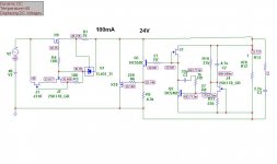
If its 1.2A max then the following schematic should be OK for the CCS current setting. If there is any doubt:
Use a DVM in current mode between reg's output and SB's input to see the max load draw and allow +200mA so the reg stays warm enough and the sinking goes small size. The CCS Mosfet will give 10W heat dissipation, the shunt Mosfet 1W. Total running current is Q7Vbe/R1. As it is in the example can give 1.3A even if the particular transistor will give 0.61V Vbe. For 0.66V Vbe it will be 1.4A. If you check the voltage drop across R1 in the practical build, that will be Vbe. Divide by R1's measured value, that's the real current exactly in any build, not an estimation without known tolerances of Q7, R1. DON'T try it without the SB attached, it will need much more Q4 sinking, else it will overheat the shunt Mosfet hard.
Use a DVM in current mode between reg's output and SB's input to see the max load draw and allow +200mA so the reg stays warm enough and the sinking goes small size. The CCS Mosfet will give 10W heat dissipation, the shunt Mosfet 1W. Total running current is Q7Vbe/R1. As it is in the example can give 1.3A even if the particular transistor will give 0.61V Vbe. For 0.66V Vbe it will be 1.4A. If you check the voltage drop across R1 in the practical build, that will be Vbe. Divide by R1's measured value, that's the real current exactly in any build, not an estimation without known tolerances of Q7, R1. DON'T try it without the SB attached, it will need much more Q4 sinking, else it will overheat the shunt Mosfet hard.
Attachments
Wich one is ok
I have one doubt for C2 is 100uF or 1000uF?
I have one doubt for C2 is 100uF or 1000uF?
An externally hosted image should be here but it was not working when we last tested it.
An externally hosted image should be here but it was not working when we last tested it.

!
Currently drawing board for this new shunt, CCS has been taken from ikoflexer, shunt from Salas version V1.2. Here is schematic. I have a few questions, which mosfet's to use in cca and in shunt, but to be in to220 housing? What other substitutes can be used for 2N5457 and how much should be idss? Can I use GR classification for 2Sk170? Salas, is shunt tested without Zobel but with 100-220-470nF capacitor at the output? Do you think that there will be oscillations if we put a 100-220nF output instead Zobel? On the preamp pcb I have 220uF in parallel with 100nF, whether it be a problem for the shunt regulator?
Thank's
Attachments
Currently drawing board for this new shunt, CCS has been taken from ikoflexer, shunt from Salas version V1.2. Here is schematic. I have a few questions, which mosfet's to use in cca and in shunt, but to be in to220 housing? What other substitutes can be used for 2N5457 and how much should be idss? Can I use GR classification for 2Sk170? Salas, is shunt tested without Zobel but with 100-220-470nF capacitor at the output? Do you think that there will be oscillations if we put a 100-220nF output instead Zobel? On the preamp pcb I have 220uF in parallel with 100nF, whether it be a problem for the shunt regulator?
Thank's
Iko used that CCS in order to use same NMos everywhere in symmetric regs. Are you going symmetric? It takes enough Vin - Vout since earth its not its reference and has a cascode to keep happy in between voltages. That is no problem if the Tx is planned, can lead to more dissipation in heavier regs its one thing. That TL you substituted there is noisier than the Vbe ref he used from a fast low noise BJT by the way. I suggest you don't change his CCS design. Maybe IRF820 for CCS and IRFP9240 for shunt. I have used IRF9540 but had to change the compensation, its a difficult one. Look for something with less Ciss, Crss than 9540 in TO-220 if you can find. You never know before practice in a new combination about compensation and stoppers. It may give you a hard time until it works. I have used BF245A instead of 2N5457 successfully and GR is OK too. R6 better start with 100R BTW.
Try 0.5R & 4u7 to be more secure for the Zobel for more loads. Most secure is a 33-47uF not low esr lytic instead of the Zobel if you will be facing problems.
No, you can't use a low value plastic cap instead of a Zobel for termination, it will oscillate. About local decoupling on your client circuit and how it will react given the cabling etc, I can not guess. Scope is your friend and your goal is to look locally terminating the shunt with best Zobel or lytic for no oscillations given the load.
There will be a symmetric version, +/-24V or +/-15V(for another preamplifier).You know that I made symmetrical V1 shunt regulator? Something similar will be now. Ok, now I'm at the stage of designing a PCB, we will see later for transistors ... I have no oscilloscope at home, only have the opportunity to go to university and there to test, but it's complicated...
Yes, I remeber the one with the long leds Vref sub boards. Where did you apply that? Content with the performance?
Its a nice endeavour to make a new combination, but you will need luck too. Good luck then.
Yes, hightech Vref! I used V1 in preamplifier, FlatBT audiophile grade audio preamplifier from "boraomega". Everything is now packed in one box and will serve for the system B. Unfortunately, it's not tested. Thank's Salas. The next day I'll show the picture to see how I imagined pcb.
- Status
- This old topic is closed. If you want to reopen this topic, contact a moderator using the "Report Post" button.
- Home
- Amplifiers
- Power Supplies
- The simplistic Salas low voltage shunt regulator