78/79XX = 5
317/337 = 6
SSSreg v1.0 =10
SSSreg v1.2 = 10+
(estimated, but close)
Really SSSreg are playing in major league, like audiophiles will said: high-end

I just wonder, could you people judge, give rating for a : 78XX, LM317,Salas low shunt 1.0, 1.1, 1.2 ? For usage in a Phono stage and DAC.
Don't forget preamps
Wow, MOAS : Mother of all shunts
IMO
78/79XX = 5
317/337 = 6
SSSreg v1.0 =20
SSSreg v1.2 = 30+
k170 and f244 are dgs.
A few manufacturers stick with this same dgs for the f245 but others use gsd & sgd.
Check your actual FETs
Oh, I see what you mean, my BF245C is from Fairchild, so according to their datasheet it's gsd.
Thanks,
Fedor
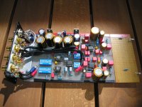
Hi guys, I need a little advice. Just finished assembling 5v and 3.3v versions of v1.2 reg, checked their output with the scope - the line is straight, no ripples (at 0,01v per square), but, I hear some sand in the highs, can it be because of the output config? The regs are feeding DAC chip, ASRC chip with clock and SPDIF input chip. One 5v and 3.3v are using 4.7uF and 1Ohm, other 5v is using 10uF and 0.5Ohm network. Will it be better to use electrolytics?
P.S. Is there any special technique for checking the output with the scope?
Thanks,
Fedor
P.S. Is there any special technique for checking the output with the scope?
Thanks,
Fedor
How you made the 3.3V? BJTs? What type? I got to see if its OK in Spice first.
Sweep the scope to its lowest us too, so you see all frequencies. Remote sensing implemented?
Hi Salas, I've made it with BD140, just as you've suggested for v1.0. Yes, remote sensing is implemented. Will try with the lowest us today.
What's the max frequency on your scope? Perhaps you got some oscillation going on that's beyond what your scope can show?
Hi Ikoflexer, the scope is little old, so the max frequency is 5MHz. Is it too low?
Thanks,
Fedor
If you got oscillation at 10MHz, you're not going to see it. But then it's not something that you can hear. Possibly though it can still affect the proper operation of the transistors.
That same thing that you hear in the highs, you cannot hear it when your system is powered without the regulator?
That same thing that you hear in the highs, you cannot hear it when your system is powered without the regulator?
Fedor, I looked in it, and your problem is that you used a BJT shunt element to avoid Vgs 4V and go Vout very low, but the buffer won't allow the error amp JFET active load any voltage margin to speak off. Gone is the nice Vgs-Vbe breathing space. So your loop gain is tremendously low, and you got joke regulation and Zo. No oscillation you can see, looks logical. Gritty sound because of no regulation almost. What changes you can test to rectify the situation I show attached. Bye bye buffer and a Cdom change. It will not be a real 1.2 but it will be decent if it will work OK firstly. Use 10R base stopper again if you use a CCS BD140 too.
Attachments
If you got oscillation at 10MHz, you're not going to see it. But then it's not something that you can hear. Possibly though it can still affect the proper operation of the transistors.
That same thing that you hear in the highs, you cannot hear it when your system is powered without the regulator?
Hm, I see your point about frequency, well, let's hope there's nothing terribly wrong after 5MHz
Well, I can only say that this was not happening with v1.0 of the reg. Don't remember how it was with original LM317 regs. But, maybe I started hearing some other weak spot of my DAC after reg upgrade, or it's my bad implementation. Anyway, apart from this, v1.2 is definetely a step up from v1.0, I hear more space in sound, bass is better, some other good things which I can't really describe for the lack of words.
Oh, and another question - if I decide to try electrolytics, do I need to change only C3-R12 network, or C2-R10 also?
Thanks,
Fedor
Fedor, I looked in it, and your problem is that you used a BJT shunt element to avoid Vgs 4V and go Vout very low, but the buffer won't allow the error amp JFET active load any voltage margin to speak off. Gone is the nice Vgs-Vbe breathing space. So your loop gain is tremendously low, and you got joke regulation and Zo. No oscillation you can see looks logical. Gritty sound because of no regulation almost. What changes you can test to rectify the situation I show attached. Bye bye buffer and a Cdom change. It will not be a real 1.2 but it will be decent if it will work OK firstly. Use 10R base stopper again if you use a CCS BD140 too.
Thank you so much for research. I will try to implement it, so, just to clarify, I need to:
1. Get rid of Q8 and R7 from original scheme
2. Change C1 33p to 1n (ceramic NP0, right?)
3. Get rid of R8 from original scheme
4. Q6 should be changed to 2sk170, or 2N5457 could stay?
Thanks,
Fedor
- Status
- This old topic is closed. If you want to reopen this topic, contact a moderator using the "Report Post" button.
- Home
- Amplifiers
- Power Supplies
- The simplistic Salas low voltage shunt regulator