See post 1893 for the latest version (two right hand schematics). You can trim Vout up to +/- 22 V. Reduce Vin accordingly for 12 Vout: around 19 Vin should be OK.
Or use the DCB1 symmetric regs (search thread) adding 1 led to the Vref array (6 instead of 5)
P.S. Salas might be busy today looking for a vuvuzela for the big match tonite!")
Or use the DCB1 symmetric regs (search thread) adding 1 led to the Vref array (6 instead of 5)
P.S. Salas might be busy today looking for a vuvuzela for the big match tonite!
Last edited:
small guide for V1.2
Small guide for V1.2

Check also this pcb picture for different volts output, pay attention for the sense wires, and the choise of output caps !!!
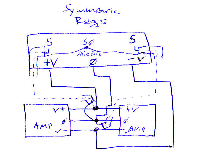
The sense wires for symmetric regs
Prefered reg for less than 5V output
CCS current adjustment, and some other details...
In addition read all the posts after the #1893 post for more details!
Small guide for V1.2
That is what it was developed for.
Anyway, guys remember if you will try to listen for output terminations. 3 steps:
1. 22-47uF solo lytic medium ESR across output. Most immune to reactive loads, most predictable for noises/oscillations if you can't check out the system with scope. Less bandwidth (talking MHz not audio), excellent phase margin (75deg), not so smooth phase undulation though.
2. 10uF+0.5R (1R//1R) Zobel across output. Very good BW, same phase margin, smooth. Film cap of choice.
3. 4.7uF+1R even more BW and 10 deg less margin but in best balance, given the load is not weird. Film cap of choice.
Check also this pcb picture for different volts output, pay attention for the sense wires, and the choise of output caps !!!
The sense wires for symmetric regs
Prefered reg for less than 5V output
This is what we have made for a turntable DC motor and works for long now. Adapt it in yours, if you got remote sensing, LEDS CCS etc.
Key points are R7,D1,R6,Q4. Can drop in any V1.0 configuration.
Yes, C2 I am talking as MKP Vref cap, your choice. For the 33pF use C0G/NP0 or Silver Mica.
In between 22 to 47uF there is always 33uF. Normal electrolytic. Not those super low ESR, not MKT/MKP.
Use a Dale for 27k Rref. The others can be generic.
R1 is setting the CCS current 0.6V/R1=CCS current. Use 1W single resistor.
The noise floor isn't high at all, its good to have place for a fixed resistor to replace the trimmer after fixing permanently, a wiper is a moving contact, not ideal guarantee. That could a Dale too.
CCS current adjustment, and some other details...
In addition read all the posts after the #1893 post for more details!
Last edited:
Small guide for V1.2
Check also this pcb picture for different volts output, pay attention for the sense wires, and the choise of output caps !!!
Nice summary thanks! Can you point me back to the post for the pcb artwork (seperate top and bottom layers) ?
Thanks.
Ken
Hi Salas, I've just assembled and started 5V version of v1.2 reg (used the schematics for +15V, without LEDs), and have a couple of questions:
1. I have some voltage drift, on startup it's 5.00V and after half an hour it's 5.04V and so on. Could it be because of a lousy trimpot? Or from the heat ?
2. My heatsinks are really hot, I'm using these, are they too small?
3. I've changed Vref to 15K and R6 to 2K2 as you've said earlier in a post related to LED version. Is this correct for my case?
Thanks,
Fedor
Hi Fedor
V1,2 without EL caps, take 30 min to settle for final voltage.
Anyway I believe you heatsinks are too small...... Heat variations do affect vout.
Oh, I see, thank you so much, will check after hour or two of work. And will have to think about some better cooling.
Thanks,
Fedor
Oh, I see, thank you so much, will check after hour or two of work. And will have to think about some better cooling.
Thanks,
Fedor
Please see Salas advice 1CW:
http://www.diyaudio.com/forums/powe...-voltage-shunt-regulator-263.html#post2220459
Where to buy:
HEAT SINK, 1CW - 345AB1000B - ABL HEATSINKS
Photo:
An externally hosted image should be here but it was not working when we last tested it.
Hi Salas, I've just assembled and started 5V version of v1.2 reg (used the schematics for +15V, without LEDs), and have a couple of questions:
1. I have some voltage drift, on startup it's 5.00V and after half an hour it's 5.04V and so on. Could it be because of a lousy trimpot? Or from the heat ?
2. My heatsinks are really hot, I'm using these, are they too small?
3. I've changed Vref to 15K and R6 to 2K2 as you've said earlier in a post related to LED version. Is this correct for my case?
Thanks,
Fedor
Draw and post what circuit you finally made so I can see if there are things that could be chosen better or not.
About the pcb, I beleive there is a mistake (I can't find Q2 2N5459) also its difficult to follow the changes of the resistors!
Here what Salas said about the resistors values vs output!
I think its nice up to where we addressed it from first draft. I don't know more about PCB tricks so no new comment from me. If someone spots something wrong, please comment.
I want to say something about the two 3K3 resistors in the CCS part. Those form a voltage divider so to bias the transistor cascode and feed its LED. Since they are referenced to Vout, there is a scale depending on what voltage region we use the reg, so to always have proper mA through the LED.
For 5Vout use 470R (use Vref 15K instead 27K, use trimmer 3K3 instead 1K, use 2K2 instead 4K3 R6, also when with JFET cascode)
For 10Vout use 1K (use Vref 15K instead 27K, also when with JFET cascode)
For 15Vout use 2K2
For 25Vout use 3K3
For 35Vout use 3K3
For 45Vout use 4K7
Please see Salas advice 1CW:
http://www.diyaudio.com/forums/powe...-voltage-shunt-regulator-263.html#post2220459
Where to buy:
HEAT SINK, 1CW - 345AB1000B - ABL HEATSINKS
Thanks Merlin, but those guys are too big for my case, maybe will have to bolt the MOSFETs to the bottom or something
Draw and post what circuit you finally made so I can see if there are things that could be chosen better or not.
Sure, will post soon with the circuit.
Thanks,
Fedor
here is a useful reference to give you an idea about what you need for mosfet cooling. look under BOARD AND HEATSINK section. just use the following formula at the bottom:
Tj = Ta + (P * (Rjc + Rcs + Rsa))
The β22 Stereo Amplifier
Tj = Ta + (P * (Rjc + Rcs + Rsa))
The β22 Stereo Amplifier
Last edited:
here is a useful reference to give you an idea about what you need for mosfet cooling. look under BOARD AND HEATSINK section. just use the following formula at the bottom:
Tj = Ta + (P * (Rjc + Rcs + Rsa))
The β22 Stereo Amplifier
Thanks, that's really useful formula indeed.
Thanks,
Fedor
About the pcb, I beleive there is a mistake (I can't find Q2 2N5459) also its difficult to follow the changes of the resistors!
Here what Salas said about the resistors values vs output!
Its correct for R2 as in the guide and for the other optimized resistors. That is with BJT cascode, hence the resistor changes for running correct current through the LED for given Vout targets. That is why you see no FETs for the CCS tail cascode. But it can go high in voltage.
Its correct for R2 as in the guide and for the other optimized resistors. That is with BJT cascode, hence the resistor changes for running correct current through the LED for given Vout targets. That is why you see no FETs for the CCS tail cascode. But it can go high in voltage.
So which version do you prefer (for lower voltage output), is there any big difference?
In addition some resistors need to be changed for different 5v-10v-12v output?
Thanks
Last edited:
There is no big difference in PSRR. Its a practical matter. Either you have a stash and sort out FETs when you need Vout in the low 20s or higher if you get a top cascoding FET more than 25VDS max with >-1.5 Vp >7mA IDSS for working alright with the 2SK170BL under it, or you use BJTs where the Vmax is very high bcs they cascode in a totem, but you would need to choose the better value resistor divider not to overdrive or starve the LED. No big deal. Oh, it shines power on too.
Hi Salas, here's the circuit. R6 changed to 2K2 and R10 to 15K, R13 is 4K7. C2 and C3 are 4.7uF MKT generic caps. Q2 is BF245C, everything else is by your schematics. Red trace is the jumper wire.
Please see if there's anything wrong.
Thanks,
Fedor
An externally hosted image should be here but it was not working when we last tested it.
Please see if there's anything wrong.
Thanks,
Fedor
Last edited:
check the pin outs of the bf245. Some are different from k170 and f244 which are the same.
Hi Andrew, just checked with BF245 datasheet, pinout seems correct (DSG)
Thanks,
Fedor
- Status
- This old topic is closed. If you want to reopen this topic, contact a moderator using the "Report Post" button.
- Home
- Amplifiers
- Power Supplies
- The simplistic Salas low voltage shunt regulator