Gopher: What you have written is true of any power supply system, not just this project. No matter what, the end user will have to use good layout, decoupling, etc. practices. But that's not the point of this project. So please stop dragging it out of context. If you really want to contribute something, start a different thread and share with all how you deal with these things in your designs and/or mods.
Jean-Charles: Please start your topic in a different thread. Let's keep this one relevant and focussed and bring it to a conclusion.
Yes, I guess you're right, you're so much smarter than me and I really should just hang it up, hand this project over to you and go back to playing tennis. At least there I know what the score is and whether the ball is in my court or not.So jbau, you see there are far more variable than you have imagined in this
Jean-Charles: Please start your topic in a different thread. Let's keep this one relevant and focussed and bring it to a conclusion.
jbau - this isn't a personal attack on you. Why should it be? I'm trying to point out that what appear to be reasonable conclusions based on what you have done are merely a small subset of a much larger picture.
It's not possible to draw the conclusions you have based on the experiments performed to date because there are more parameters than you have considered in the mix. That's the only point I'm trying to make.
Let's draw a line under the petty argument and get on with improving the audio experience. Unfortunately, LM317/337, no matter how tweaked, isn't where it's at.
Gopher: You are clearly not interest in this thread's topic. Please go away and leave us in peace with making our substandard 3-terminal regs as good as possible. Go start a new thread and show us how you deal with that larger world of variables. Oh, and provide some measurement data to back up your work.
The equipment I'm upgrading doesn't have room for anything other. That was made clear at the very beginning. That defines the limitation I'm working within. I can live with that.
The equipment I'm upgrading doesn't have room for anything other. That was made clear at the very beginning. That defines the limitation I'm working within. I can live with that.
the inductive output impedance of the LM317 + any output inductance due to pcb traces etc. forms a resonant circuit with the output capacitor. The degree of damping of that resonance depends on the ESR of the capacitor and the resistance of pcb traces between the output of the reg and the output capacitor. This is why plonking an ultra low ESR 'audiograde' electrolytic on the output of a reg can lead to hit and miss results. It all depends on circuit layout, specifically track resistance. Sometimes it sounds good, sometimes it doesn't. Generally it's a bad idea unless you have sufficient pcb track resistance to damp the resonance.
Though I'm unhappy that the excellent technical points being raised by you and jbau have embedded inappropriate personal stuff (and would request that you both try to leave that out), the very pertinent stuff technical stuff here can't be overemphasized. The regulator system has to be designed as a system, and lower is not always better when it comes to things like ESR or dissipation factor (to pick two common targets).
I'm still personally unclear on why a flat impedance is more desirable than an impedance which is just low everywhere. If I could verifiably hear a difference between a circuit being fed from a power supply with a source resistance of 1 milliohm versus 20 milliohms, I'd be more concerned with fixing the circuit.
Well I tried Sy and got the brush off. Never mind.
Back to the important stuff.
If you have one pair of regs per opamp, what matters is that the impedance is flat over at least the audio band and preferably an octave higher. The absolute value of the impedance isn't that important since you only have the one opamp to power. It's far easier to design a reg with wide bandwidth by using less feedback in the comparator and accepting the inevitable consequence of a higher output impedance.
If you have one reg feeding two or more opamps then a very low output impedance is more important than flatness (both would be nice but difficult to achieve with feedback) since the current draw of the other opamps will impose a signal on the one you're looking at through the shared regulator. The lower the output impedance of the reg the lower will be that shared signal and the more it can be attenuated by the opamp's PSRR.
What is "just low everywhere"? That's a pretty imprecise descriptor. Part of the point is, you don't know if your supplies are "just low everywhere" or not. Or if they're equally "just low" or not. It's blind faith that they are. So I'm putting numbers to it. And listening. And hearing a huge difference. And waiting patiently for someone else to do it instead of saying what they think.SY: I'm still personally unclear on why a flat impedance is more desirable than an impedance which is just low everywhere.
But until then, is there a power delivery situation in audio where a flat and low source impedance/phase isn't a good thing? Every one I've ever encountered, nonlinearities in either the source/load were reflected in the output. How can it be otherwise.
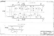
Wavetek thinks flat supply impedance/phase is important. Their 288 function generator uses 317/337 with lots of support circuitry to get the system impedance flat. But the way they do it, the 317 is 0.2 ohms higher than the 337. I can post a schematic if you wish.
Well SY, you can test that one out easily. Build the circuit, and listen. It's almost trivially simple.If I could verifiably hear a difference between a circuit being fed from a power supply with a source resistance of 1 milliohm versus 20 milliohms, I'd be more concerned with fixing the circuit.
I am still the only person who has built this and heard what it does. mjf built one that is close, but too many things are different to say if it performs the same or not. One of these days someone will stop just throwing their opinion at this and actually do something. I can tell you that one audio manufacturer will soon do just that. They have been intrigued enough by this project to buy the necessary equipment to test it for themselves.
Mr. Evil,
this is academic. A 10mR peak at 5kHz within an overall Zout of 100uR surely doesn't matter at all. It's flat enough because it's low enough.
--------:--------
jbau's point (and mine, too) seems to be that the textbook 317 circuit is far from optimum (and IMHO the datasheet is full of very misleading stuff on component values selection) and there is room for big improvement with little effort and low cost.
I, like maybe many others, have both built and simulated a bunch of 317 circuits (including the EDA test circuit I just simmed now, which gives pretty consistent results with any of the three 317 models I have).
A "typical circuit" with Cadj=0 and Cout=10uF has chances to exhibit a sharp impedance peak at ~5kHz which can go up to tens of ohms. The load step reponse looks correspondigly horrible.
With a bit of tweaking (a few passive parts) one can get a really flat Zout of ~100mR from 10Hz to 100kHz. Here Gopher is right on track, the point is to compensate the 1uH (or thereabouts) output inductance of the basic circuit. Which is easy when you know the LF output resistance... and still easier if you override both with passives to get stable, predictable conditions for this ESL/ESR. It's essentially the same problem as with paralleling different caps, the parameters of the smaller one have to be choosen such as to compensate the ESL of the bigger one. And Cadj basically lowers Zout on the LF side, that's why we need a rather big time constant there. Its ESR/ESL doesn't matter much. Er, this is only my 2cts, YMMV.
Of course all depends on the circuit it powers. Single ended, supply referenced stuff is very likely to have poor PSRR.
-------:---------
jbau, I'd really like to see the Wavetek 3x7 circuits if you are willing to share. There is always something to learn.
- Klaus
Evil, I thought I'd explained this in bits here and there, but we'll try again. There are many reasons and I probably won't hit them all. Gopher explained one a couple posts back, where multiple devices share the same rails. Add to that, power supplies are ideally constant-voltage, current on demand. But that only exists in theory. They all have finite source impedances which define their ability to deliver current. And it isn't just one number. It's multiple curves that change as a function of current level, frequency, probably other things. The devices drawing current from it look back at the supply through a transmission system that also has non-flat impedance. Current drawn through a source that isn't a flat impedance will modulate the voltage where the impedance is higher. With solid state devices, this happens as frequency increases. Unfortunately, most circuits have poorer PSRR as freqs increase. Add to that, phase matters. Reactance alters timing relationships, so current doesn't arrive when it's demanded at all freqs. That is why I generalize, the tonal response in most systems ends up resembling the impedance curves of the power systems in it.
Add to that, in a bipolar supply system, if the negative supply has different impedance curve than the positive, that's an even greater mess.
I agree with the conviction that, AT SOME POINT, a low-enough impedance will render it all a moot issue.
But where is this point? What is "low enough"? And is it "low enough" across the audio band and maybe a bit beyond? Do you know? If so, how do you know? Noone has answered that yet. And the reason why is simple: they can't, because it's work they have never done.
I'm coming into these questions open-minded because I don't have the answers. I see issues that I've had to grapple with in other systems (speakers, transformers) with great success, and I think I'm approaching it with tools and techniques appropriate to the task. What I have discovered so far, is that flat matters. Low matters. And equal matters. Just how flat, how low, how equal, I don't know.
For my speakers, I have freq response, phase, impedance, harmonic distortion and dynamic linearity data for them so I know how they behave. This is the first time I've ever listened to a program source of any kind where I knew the Z characteristics of it's analog supplies. Up until now it's been an undefined variable.
I'm going to give a little more time to this project, and then I need to install these into the pieces that I'm upgrading and move on to the next project. Time management also matters. And sitting here fighting off the crap being slung at me by people who should know better feels like a huge waste of time. It's exhausting.
Now this depends so much on the powered circuit that any generalizations seem impossible. Say we have a standard opamp circuit which will operate in class A/B. Then we have rectified load currents in the rails, which can have pretty sharp edges depending on how sharp the A/B-transition is. Hence the bandwidth of the supply should be significantly higher than the audio range, I normally try to achieve a x10 factor, 200kHz. And the region above that (up to a bit beyond the GBW of the opamp) must be handled by local decoupling at any rate (preferably L-C or Ferrite-C, not a C alone -- the parallel cap issue again).jbau said:But where is this point? What is "low enough"? And is it "low enough" across the audio band and maybe a bit beyond? Do you know? If so, how do you know? Noone has answered that yet. And the reason why is simple: they can't, because it's work they have never done.
The +/-rail asymmetry can be handled by using identical circuits for both rails, requiring individual secondarys and bridges/filters of course and only feasible with a single global supply.
- Klaus
KSTR,
I don't have the luxury of using a discrete supply in these equipments. I'm stuck with a 3-term reg, that's why I'm doing this.
I've attached the +-22V supply drawing from the Wavetek 288, the 12V circuits are the same except some different resistor values.
I don't have the luxury of using a discrete supply in these equipments. I'm stuck with a 3-term reg, that's why I'm doing this.
I've attached the +-22V supply drawing from the Wavetek 288, the 12V circuits are the same except some different resistor values.
Attachments
jbau, just a procedural point- when someone is posting as a moderator, the cop icon is shown. No cop icon, it's just another member.
I think I asked a pretty reasonable question- why would you want to use a circuit with terrible PSR? If you want the output impedance to be flat, stick a 0R5 resistor on the output.
And seriously, do get the Dietz paper I referenced earlier. He covers very thoroughly the points you're trying to explore here. Pease elaborates on it in his superb book (which you should also have, and which has the Dietz paper as an appendix).
")
Attachments
SY said:jbau, just a procedural point- when someone is posting as a moderator, the cop icon is shown. No cop icon, it's just another member.
I think I asked a pretty reasonable question- why would you want to use a circuit with terrible PSR? If you want the output impedance to be flat, stick a 0R5 resistor on the output.
And seriously, do get the Dietz paper I referenced earlier. He covers very thoroughly the points you're trying to explore here. Pease elaborates on it in his superb book (which you should also have, and which has the Dietz paper as an appendix).
Hi Sy, i don't want to put words in jbau's mouth but i think one of the important aspects of his argument is that the impedance not only has to be low enough but also benefits from being matched on the positive and negative rails.
An alternative idea is that when it Zout is not low enough matching becomes important.
Earlier, i suggested putting a resistor in series with one of the legs of the PS to deliberately unmatch the positive and negative sides and then repeat the THD test or a different test. I still think this is a good idea.
Would you also mind commenting on what you consider "low enough". If this is too general a question could you comment on some of the design parameters that allow you to determine what is low enough?
One final point for this post, in this thread i have commented several times about the effect of ESR (gopher has repeated this point) mainly because i have read the dietz article. My understanding is that the changes jbau has made are not that sensitive to ESR. Jbau, please correct me if i am wrong.
- Status
- This old topic is closed. If you want to reopen this topic, contact a moderator using the "Report Post" button.
- Home
- Amplifiers
- Power Supplies
- Another look at the LM317 and LM337 regulators