Over the past few weeks, I have been searching the forum for info on determining current ratings, etc for unknown transformers.
I was reading a thread about 2 weeks ago where someone had posted an article from an old electronics world magazine about the subject. To make a long story short, I managed to download the first page of the article to my HD but did not get the remaining pages before being interrupted and then having my computer reboot while I was away from it, losing the thread.
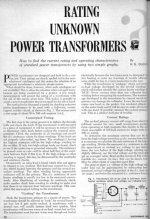
I have attached the first page of the article and I am hoping that someone has the second page (or can point me to the original thread) so that I can download it also.
I had to laugh when checking the "have you searched" button to post this......yes, I searched my A$% off!!
I was reading a thread about 2 weeks ago where someone had posted an article from an old electronics world magazine about the subject. To make a long story short, I managed to download the first page of the article to my HD but did not get the remaining pages before being interrupted and then having my computer reboot while I was away from it, losing the thread.
I have attached the first page of the article and I am hoping that someone has the second page (or can point me to the original thread) so that I can download it also.
I had to laugh when checking the "have you searched" button to post this......yes, I searched my A$% off!!
Attachments
Follow the trail, starting here:
http://www.diyaudio.com/forums/showthread.php?postid=1467962#post1467962
http://www.diyaudio.com/forums/showthread.php?postid=1467962#post1467962
Just for giggles, I just searched the tubes forum for "transformer current" again since the thread you link to above is called "transformer current question" started by mikecj.
The thread above does not show up, however, another thread started by whitelabrat shows up that is also called "transformer current question".
So there are two threads with the same name but only one shows up in the search.
The thread above does not show up, however, another thread started by whitelabrat shows up that is also called "transformer current question".
So there are two threads with the same name but only one shows up in the search.
A rough estimate can be made based on the core center cross sectional area.
I've got a book with a table at home.
The issue is that it only gives you the total power rating of the transfromer, but can not determine the split between windings of a multiple output transformer.
I've got a book with a table at home.
The issue is that it only gives you the total power rating of the transfromer, but can not determine the split between windings of a multiple output transformer.
Last edited:
You could get a reasonable estimate by measuring the winding resistances accurately (subtract out meter lead R, you may need a 4 contact point Kelvin clip milli-Ohm meter for the LV filament windings) and also recording the winding voltages. Figure about 15% IIR loss for the combined windings (half of that in the primary). And figure the same X% voltage drop (from winding R) allowed on each winding at it's max current (including the primary R drop accounting for another X% at full xfmr load) which (when totalled up for all the windings) matches the 15% IIR total loss (heat limit). Some simultaneous equation solving to do then.
Last edited:
I would go by trial and error.
Feed the transformer from a variable transformer set to the marked input voltage and check the voltage before and after all of the tests
First test the off load voltage of the first winding and all being well it should be slightly above the marked rating. This will be the marked voltage plus the regulation percentage.
Repeat the tests for all other windings.
Next test. Run the winding on load with enough RESISTIVE load in order to bring the voltage half way down to the marked rating.
Repeat this test for all windings.
Then put all the loads on at once and see how close you get to the marked voltage. From this you should be able to make a pretty good estimate.
Most transformers that are worth saving will be 10% regulation. Wall warts are usually 20% regulation and are usually only used to power junk anyway.
Last edited:
")
I had a 400Hz three phase power supply for a 1KW linear for the HF rig on a P-3A/B Orion let go on the bench once. Molten copper splattered across a brand new set of Bausch and Lomb Photo-Gray Aviators.
Best money I ever spent on a set of sunglasses.
Ouch that must have been a big "pop".
Did they all survive?
- Status
- This old topic is closed. If you want to reopen this topic, contact a moderator using the "Report Post" button.
- Home
- Amplifiers
- Power Supplies
- Determining ratings for unknown Power Transformers