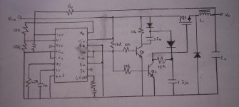
I'm in the process of building an SMPS for a computer, which will run off 11-14v, using an LM3524D chip running at ~25kHz. I have modified the design from the datasheet to include a voltage doubler, so that I can drive a high-side NPN mosfet (IRL2203N), which I have laying around. Q1 and Q2 are both C945 NPNs. Q1 drives the voltage doubler, while Q2 switches the doubled voltage to drive the gate of the mosfet.
The target output voltage is 3.3v, with a max current output of 9A (according to the current SMPS). The inductor I would like to use is a 184uH that I pulled from another SMPS. On to a few questions.
The formula for calculating the value of L1 is 2.5Vo*(Vin-Vo)/(Io*Vin*Fosc). Which values do I use if my input voltage is variable (11-14v) and the output current is also variable (0-9A)?
How will the output be affected if the inductor value is too low or too high?
Attachments
Output capacitor, output inductor, and frequency compensation of the control loop are all related.
You usually find an output inductor value that produces reasonable current ripple for the chosen operating frequency first. Then you select output capacitor for the desired resonant frequency and output ripple voltage, then you compensate the loop with a zero at that frequency.
If you do the math, 22uH results in +/-2.17A ripple for 12V input, 3.3V output and 25Khz. The inductor should not saturate until 9+2.17= ~11A and current limit should be set slightly above that.
(12-3.3) * (3.3)/12) * (1/25000) / 22e-6 ~= 4.35A p-p (+/-2.17A)
A 1000uF output capacitor would result in 1073Hz resonance, a reasonably low frequency. You would need 1000uF of low ESR capacitance with 2.17*.577=1.25A overall ripple current rating (maybe better two 470uF or three 330uF). The .577 is the factor to get the RMS value of a triangle wave from the amplitude.
1 / (2*3.1415* sqr(1000e-6*22e-6) ) = 1073Hz
- Status
- This old topic is closed. If you want to reopen this topic, contact a moderator using the "Report Post" button.