Hi everyone, I've built a 250W Half bridge SMPS that works fine on its own, but when I unify its ground with the ground of another SMPS (this is just shorting the ground of one with the other so they are referenced to the same ground, the PC's PSU for instance), my SMPS becomes noisy and unstable, the questions are:
--Why is this happening? is it got to do with the fact of the power supplies work at a different frequency?
--Must their grounds be coupled instead of unified?
--My SMPS' primary side ground is not coupled to earth GND or the secondary side GND, can this be the problem? if so: How do I select the coupling cap, I did'n couple the primary and secondary ground because once I coupled a flyback SMPS i've built and blew up on power on, obviously worked fine before
I've searched the forum for something alike but found nothing... Hope you can help me
Regards to you all, Fernando
Hi
Don't use the word ground. Using the term ground is just confusing things (there are many grounds esp. with 2 supplies together)
5 connections per supply
input source and return
output source and return
chassis
Look into common mode chokes to control where you want noise to go or stay. The noise of one SMPS make take the path of least resistance were you don't want it to go..like the chassis.
Well Infinia, thanx for the help and sorry for the misuse of terms:
input return is what I called "primary ground"
output return would be "secondary ground"
chassis is "earth GND"
Hope with this info and corrections U can help me better... I look for "common mode chokes"
Thank you!!
input return is what I called "primary ground"
output return would be "secondary ground"
chassis is "earth GND"
Hope with this info and corrections U can help me better... I look for "common mode chokes"
Thank you!!

don't be sorry.
It's not your fault that the industry misuses the the term ground for all things that are not the earth we stand stand on, or get buried in.
I do agree that we should treat EACH CIRCUIT as as a loop, the current must flow and return. It cannot do anything else.
Your job is to allow those flowing and returning currents to pass without interfering with each other.
If calling each circuit by a unique name helps in that process, then use it to help you understand what you are trying to achieve.
Thank you all, by looking into the common mode chokes I solved the problem quite well, I completed the input filtering circuit by adding a cap before and after the input choke and after this choke a cap beetween each of the mains line poles and chassis, this filtered quite efficiently and there are no more interference
If you want, I can post the circuit as it is now
Regards, Fernando
If you want, I can post the circuit as it is now
Regards, Fernando
chimi said:Thank you all, by looking into the common mode chokes I solved the problem quite well,...
Hi Fernando
Congrats and glad you fixed your problems. I would be happy to see your circuits.
AndrewT said:I expect you used X & Y rated capacitors on the mains connections.
For the moment and only for testing purposes, I'm using standard 400V rated polyesther caps, since I couldn't get the caps I wanted to test with...
Which are X and Y capacitors? What voltage rating should I use? I understand it's in the order of kVolts
here is the input filtering circuit along with the rectifier bridge
Regards!
Attachments
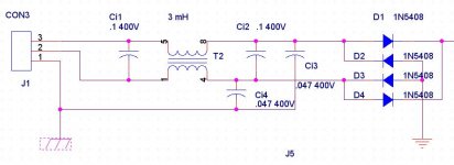
Ci1 and Ci2 must be X rated.
Ci3 and Ci4 must be Y rated.
The voltage must exceed your maximum mains voltage.
Here in the UK we use 275Vac because our maximum voltage is 254Vac.
250Vac X & Y rated are also available.
47nF to earth will allow a high earth leakage current.
It's more usual to use <=10nF to earth and many EMI filters use 2n2F
Ci1 can be fitted at the mains distribution board and can be upto 10uF
- Status
- This old topic is closed. If you want to reopen this topic, contact a moderator using the "Report Post" button.
- Home
- Amplifiers
- Power Supplies
- problems unifying grounds