Hi guys.
I'm building my next power supply and I need to clarify something.
If I parallel multiple rectified AC after a transformer's secondary , is it considered isolated?
I originally intended to use 1 transformer for each output but I find that it's a waste of money and space due to the low current I intend to supply for about half of the 10 outputs.
e.g.
Code:
AC->(1) Rectified DC->Smoothing+Filtering+Regulation
  ->(2) Rectified DC->Smoothing+Filtering+Regulation
  ->(3) Rectified DC->Smoothing+Filtering+Regulation
  ->(4) etc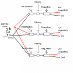
firethorn said:Haha... I myself thought I sounded cryptic..
Apologies for the bad drawing. I can't draw for nuts, on a computer AND in real life. haha.
Is the schematic below considered "isolated" or isolated? There is only 1 secondary.
Isolation is with respect to the mains service; so it is isolated.
firethorn said:I mean with regards to ground loops. Not in terms of safety. Is it considered isolated in that respect?
My experience with personal equipment has involved ground loops being caused by interaction with the mains. Yet there is just about an infinite number of possible set-ups. Maybe just try minimalism and address problems as needed.
You seem to miss something elementary.
3 times 9V supplies are not isolated in any way, because you achieve isolation by magnetic (or optical) coupling only. Keep in midn that normally you connect GND to one of secondary wires.
But you can achieve ground loop braking by some common mode filtering, I mean if you put R+L on both wires of rectified voltage and C between them after RL.
---/\/\/\/---ununun---|----------
..............................|
............................___
........................... ___
..............................|
---/\/\/\/---ununun---|----------
You are allowed one isolation card with that scheme. When any one of the 9V commons gets tied to ground, the others automatically follow this reference, though you need to understand the others do not have their commons directly connected to ground, nor are you permitted to. Nor does the measured common-ground voltage on the other supplies equal zero, it is somewhat dynamic and variable.
So, as long as you have no ties to ground on the secondary supplies, they are isolated from ground and from the mains voltage. But they are never isolated from each other, they are bonded together through the p-n diode junctions.
You only get one opportunity to ground a secondary. So with regards to ground loops, it will fix the bonded secondary, but I doubt you will like what happens to the others.
Funny you guys should mention this because I actually get better performance from my own(well it's not really my own design) psu designas noted above than with certain other products that are truly isolated with their own individuals transformers per output.
Perhaps the combined electrical fields from the transformers have a compound effect on the nearby circuitry? But I don't wire the transformers myself. Weird.
So I guess the term isolation would involve, in all cases, a physical separation from each other.
That solves one mystery but now I'm screwed in terms of enclosure real estate unless I can wrap my head around the concept of a flyback converter and how it would work in my scenario, as suggested earlier.
Many thanks guys.
have experimented with a "manually switched" flyback and it works great....
now on to the real smps-ing.. =D
just a summary for those who happen to stumble on this thread:
- isolation involves physical isolation from the circuit... in the case of a flyback, this involves an inductor converted to a transformer..
or a really small "audio transformer" if you live in singapore and are headed to simlin. It's not really an audio transformer but it's labelled that way at one of the shops I got it from.
- if you happened to have read my previous posts, the reason why I got really quiet performance from my psu was because it was filtered really well.. too well i would say...
15vac... 1000uf filtering after shottky full bridge rectifiers. then the standard lm317 setup with about 3 caps... then a 100uf filter at the outputs.... 9vdc.. a serious waste of power.. but obviously very quiet...
if possible go for an smps.. saves a ton of space.. only if you're really serious about quality, then carry on with the lm317 setup...
Cheers.
Love this forum. =D
- Status
- This old topic is closed. If you want to reopen this topic, contact a moderator using the "Report Post" button.
- Home
- Amplifiers
- Power Supplies
- Isolation after transformer considered isolated?