So its about 20dB better with just substituting R6 for an Idss 2SK170 and absolutely no other changes? Like here in the attachment? If yes, OK no problem, I will mod it and listen carefully. The BC550C goes to 156mW with 7.5mA so it does not seem to be a problem.
Attachments
ikoflexer said:I know you don't like opamps in the regulator, so you may not like this one that I'm playing with now. But it's not very bad (see attached).
I will listen to what the JFET CCS does instead of the resistor first. On the other hand you saw the shunt + phono scope traces for noise, and my FFTs with 100Hz buzz at -107dB of shunt+phono, so I don't know what all those nice additions will practically do. But I am curious. Make the super sim and listen to it too VS your second best, would be my suggestion.
Yes, that's the only change I've made. I'd say, while simulation is fun, please let me know what happens in reality.
I have to say again, this is all academic. I too, at the end of the day like practical solutions. But man, getting another 80db improvement in the simulator beats sudoku any day for me I will put this one through a battery of tests and if it survives I'll prototype it too, nothing to lose. And, you'd be surprised how well the opa134 works in a regulator
I have to say again, this is all academic. I too, at the end of the day like practical solutions. But man, getting another 80db improvement in the simulator beats sudoku any day for me
I will put this one through a battery of tests and if it survives I'll prototype it too, nothing to lose. And, you'd be surprised how well the opa134 works in a regulator ikoflexer said:Until then, this is how it sims (jfet replaced R6).
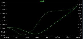
Check the loop stability, I smell trouble.
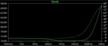
I like the soft trend of rise and phase that you simulated on the simple ones. Now if the resistor one that I have in use now, really does 74dB, if we assume 200mV peak to peak ripple from a wall wart DC in (not the fast bridge and 33R to 10mF Slit Foil that I really use), it will divide it by 5000 times. 0.04mV 100Hz ripple at the phono B+. If it only does 40dB then 2mV P2P. And then there are local RC filters...No wonder it does not buzz.
syn08 said:
Check the loop stability, I smell trouble.
Thanks Syn08. I will just install it instead of R6 and will check for real. If it burns a BJT and a Mosfet, no worries. I spend as much a day for cigs and they do me no good.
Instead I will inhale magic smoke.Could someone with experience please shortly explain what the desired behaviour is as far as transient response to changes in the load?
jwb, I tried a similar test to yours, with my simulation of the Jung regulator, attached, and then with a new regulator in the next post.
jwb, I tried a similar test to yours, with my simulation of the Jung regulator, attached, and then with a new regulator in the next post.
Attachments
ikoflexer said:salas, you may not be so enthusiastic when you learn that it is a merge of ideas from your regulator and Mr. Jung's.
To the contrary, I am honored! Jung and me in the mixer! You leap beyond Ed Wood's masterpieces even! The patriarch tech and the anarchic alchemist in marriage. Exist in sci - fi and Iko's lab, exclusively!

salas said:OK I got a partner!But we if we come back with posted photos of burned regs, syn08 rang the bell early!
Fair is fair!

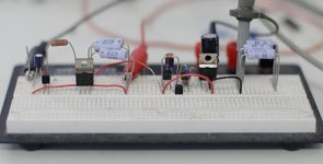
Here's my 9V version of the design by salas. I think it's brilliant.
I was forced to use IRF9610 because I don't have any power P-channel FETs on hand. The 9610 has Rds(on) about six times higher than the IRFP9240, so the line regulation is not as good. But it works! It doesn't oscillate at all, and whatever noise there may be is well below the ability of my scope to measure (also well below the noise from the bench supply input.)
I like it!

Attachments
jwb said:
First, let me thank you for the stimulating conversation.
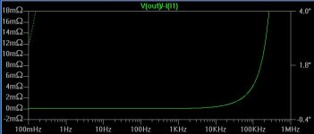
I think the entire power system needs to be addressed when looking at these regulators. For example, in the project I am working on today, there is a Jung-type regulator, but there is also an array of 8 39µF OS-CON caps, 8 1µF ceramic caps, and an 800pF capacitance due to the ground planes of the PCB. Output impedance of the whole system is < 100mΩ out to 80MHz and < 1Ω out to 400MHz, which I think is acceptable considering the passband only extends to 96kHz.
Regarding your comment, I agree the ringing was excessive in the plot I posted. It turns out that the AD825 has far better transient behavior than the AD820 (in simulation). I use the AD820 for low voltage outputs since it can swing rail-to-rail and run from a single 5V supply, and I use the AD825 for outputs ≥ 9V.
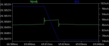
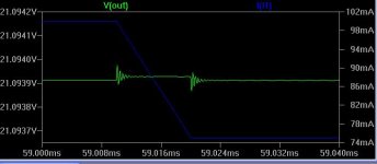
As you can see from this plot, the transient load response is rather good. For a (quite improbable) 25mA load step with a 10µs rise time, the output swings only about 10µV. That's -68dB @ 100kHz.
The real test, of course, is with the implementation: pcb trace resistance and inductance, parasitic capacitance, wiring inductance and so on. You may or may not recognize those waves in the real thing
Jan Didden
ikoflexer said:This is a new frankenstein regulator, transient response. Any comments are greatly appreciated.
This transient response is clearly better than the previous one. This DC Zout is worse than the previous one. So, take your pick
Jan Didden
- Status
- This old topic is closed. If you want to reopen this topic, contact a moderator using the "Report Post" button.
- Home
- Amplifiers
- Power Supplies
- Best low noise regulator?