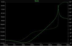
jwb said:As long as we're simulating things, I thought I'd have a look at the improved Jung regulator. The output impedance is nice: below 1mOhm from DC to 4kHz, rising to 25mOhm at 96kHz.
An externally hosted image should be here but it was not working when we last tested it.
Hi jwb, I've simulated the Jung regulator in the past, various versions, but never got such good results as you. I tend to never use perfect current sources and such, in an effort to be as close as possible to the real thing (such dreams eh?). Even so, I take my own sim result with a large grain of salt. However, I would be interested to see if your results turn out as good if you replace the perfect current sources with the proper parts. Thanks in advance.
ikoflexer: according to your simulator output, I'm sure your version of the Jung is oscillating. Try adding about half an ohm of ESR to C3.
I'm not sure how to model current diodes like Vishay J506. Those are the ones I use in practice. I shall look around for some canned spice models.
I'm not sure how to model current diodes like Vishay J506. Those are the ones I use in practice. I shall look around for some canned spice models.
Its no good simulating the output load with a sine wave - you need to use a square wave to see how the regulator responds to fast transients. This will let you get an idea of how your loop is compensated and whether it needs tweaking (you won't get the absolutely correct answer from the sim, but the sim will help you understand what is going on in the circuit and where th e best place is to tweak). The last thing needed on a high performance reg whether shunt or series pass is overshoot or ringing on load or line transients.
I'd also look at the behaviour with a squarewave on the input (say 1-2V). this will also help you get a feel for feedthrough mechanisms.
Loop compensation and feedthrough prevention on these high performance regs is the as important as all the effort on low noise design. Don't forget it!
")
I'd also look at the behaviour with a squarewave on the input (say 1-2V). this will also help you get a feel for feedthrough mechanisms.
Loop compensation and feedthrough prevention on these high performance regs is the as important as all the effort on low noise design. Don't forget it!
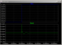
Here's the result with a .5R ESR on the output shunt cap.
As I said, I am pretty sure that the Jung regulator does an extremely good job in practice. My last attempt at a prototype was not very successful, as it oscillated like crazy. I'll probably do it again with some care as far as the layout goes.
As I said, I am pretty sure that the Jung regulator does an extremely good job in practice. My last attempt at a prototype was not very successful, as it oscillated like crazy. I'll probably do it again with some care as far as the layout goes.
Attachments
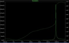
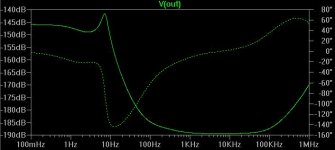
Yes, it is ripple rejection. A couple of posts back I plotted output impedance as well, shown as V(out)/-I(I1), with the Y-axis in mohms.
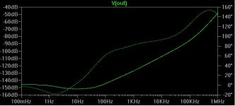
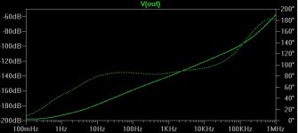
I'd like to mention a little detail which a lot of people may not realize. A humble low-pass filter at the input can make a big difference in practice. The Jung regulator especially might be a good candidate since its psrr curve raises as frequency increases. Here's the psrr plot for the ad820b version, with an LC filter (L=100mH, C=4700u) at the input.
Good night.
Attachments
Bonsai said:Its no good simulating the output load with a sine wave - you need to use a square wave to see how the regulator responds to fast transients. This will let you get an idea of how your loop is compensated and whether it needs tweaking (you won't get the absolutely correct answer from the sim, but the sim will help you understand what is going on in the circuit and where th e best place is to tweak). The last thing needed on a high performance reg whether shunt or series pass is overshoot or ringing on load or line transients.
That's true, but it's also true that the regulator is relied upon only in the region < 100kHz. The large bypass capacitor is in use from 100kHz to several MHz, and the small bypass capacitors handle frequencies from a few MHz up to 1GHz, where the mutual capacitance of the power planes handles the remainder. In my opinion, it's irrelevant how a regulator performs for load steps with rise times less than 10µs.
Also if you have large input transients you have a major architectural problem with your circuit!
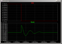
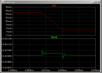
That said, I think the Jung has creditable transient performance. Here, for instance, is the response to a 1V transient with 1ns rise time on the input.
Attachments
The reason to test with a step or square wave input is to se e how th e circuit behaves wrt to line noise - and you do get spikes and straight HF noise coming through much more than you would believe. How does your cuircuit behave unde r thes e conditions - does it pass th e nois e straigh t through? does it oscillate? Its easy to deal with DC or low frequncy input voltage shifts, but at higher frequncies this is another matter.
Bonsai said:Looking at your last post, if I'm reading it correcly I'd say you have problems. There should be no overshoot or ringing.
Using a rise time of 1ns is not practical.
Use a few u seconds.
The last post is with a 10us rise (fall) time.
There are zeners with substantially lower dynamic Z than LEDs these days. I just bought a box full of 6.2V zeners with 9Ω dynamic impedance at 5mA.
FWIW: According to the book - and here I actually mean "Valve Amplifiers" by Morgan Jones - cheap red LEDs and infrared LEDs should have impedances in the range of 5 - 6 Ohms, and the new and brighter LEDs of varying colours obvioulsy have higher impedances. I think LEDs like healthy currents of 10 - 20 mA to be at their optimum (Zeners btw. too). Off course, this is all written lore and not my personal measurements.
Hi all. This is a very interesting thread.
First of all,
http://www.diyaudio.com/forums/showthread.php?postid=1759105#post1759105
The 2N6387 is a power darlington! Is this an error?
I have a simple and brutal circuit here which should suffice.
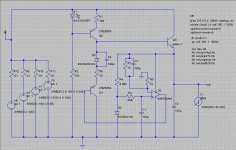
Lastly, Does anyone want to take a poke at a Rush Cascode based Shunt or Linear regulator? Here is my little stab at a shunt regulator (attached). Input regulation is very good but not as good as my linear version, which I will post if anyone wants to see it... I have not tested this circuit in real life.
I know someone will complain about thermal drift but really, is a perfect 12V output voltage at all times that important for an amplifier?
- keantoken
First of all,
http://www.diyaudio.com/forums/showthread.php?postid=1759105#post1759105
The 2N6387 is a power darlington! Is this an error?
Its no good simulating the output load with a sine wave - you need to use a square wave to see how the regulator responds to fast transients. This will let you get an idea of how your loop is compensated and whether it needs tweaking (you won't get the absolutely correct answer from the sim, but the sim will help you understand what is going on in the circuit and where th e best place is to tweak). The last thing needed on a high performance reg whether shunt or series pass is overshoot or ringing on load or line transients.
I have a simple and brutal circuit here which should suffice.
An externally hosted image should be here but it was not working when we last tested it.
Lastly, Does anyone want to take a poke at a Rush Cascode based Shunt or Linear regulator? Here is my little stab at a shunt regulator (attached). Input regulation is very good but not as good as my linear version, which I will post if anyone wants to see it... I have not tested this circuit in real life.
I know someone will complain about thermal drift but really, is a perfect 12V output voltage at all times that important for an amplifier?
- keantoken
Attachments
Bonsai said:The reason to test with a step or square wave input is to se e how th e circuit behaves wrt to line noise - and you do get spikes and straight HF noise coming through much more than you would believe. How does your cuircuit behave unde r thes e conditions - does it pass th e nois e straigh t through? does it oscillate? Its easy to deal with DC or low frequncy input voltage shifts, but at higher frequncies this is another matter.
Bonzai,
A test with a sine sweep to some high frequency showing curves of magnitude and phase against frequency gives you the same info and is often easier to interprete. I can see for instance that PSRR decreases to say 20dB at say 100kHz, or that pphase shift reaches 180 degr at say 200kHz. Looking at a ringing sq wave doesn't give me so much quantitative info. But I guess it's also a matter of personal preference.
Jan Didden
- Status
- This old topic is closed. If you want to reopen this topic, contact a moderator using the "Report Post" button.
- Home
- Amplifiers
- Power Supplies
- Best low noise regulator?