trying to operate a two transistor CCS with only 600mV is completely different from operation @ ~ 1.2V. Even better if 5Vbe is available.
Your low pinch off voltage jFET (k170) will operate better at these extremely low voltages. The high pinch off voltage jFET (BF24x) needs more voltage to operate.
And all CCS benefit from higher voltage operation, if it does not vary too much, or too fast. Cascodes then come into their own.
Your low pinch off voltage jFET (k170) will operate better at these extremely low voltages. The high pinch off voltage jFET (BF24x) needs more voltage to operate.
And all CCS benefit from higher voltage operation, if it does not vary too much, or too fast. Cascodes then come into their own.
Since we can lift the margin with a resistor or a Darlington, no worries Andrew. The trimmer gives a variable reg. Cool. If JWB fancies it he will tell us more in practice. Enough now with regs, I just got my 10M45S quartet and my hungry line stages are waiting for a Jung 317 DMosfet cascoded anode sink! Also my new ''Valve Itch'' phono with 6N2PEV & 6N8 mu stages plays nicely and I want to fix the preamps so to break it in and listen much or tweak even.
I had practical problems without the Jfet ccs under the Zref. A very low frequency cycle was pumping the woofers. Maybe 5Hz. But it may not manifest in your case, given the collector ccs change. Else I see nothing bad. Topologically it is like my very first before I ccs'ed the Zref plus the collector ccs. I know it works, I use the collector ccs. My idea was low noise and few parts. Low noise it proved to be in many guises. You have seen so too. Did you listen to it?
Maybe your very high value capacitors will save such a phenomenon. I was using 100uF when I got it, and resistive collector load.
Did you put them there in such values to avoid VLF phase twists, or you just got em handy? Also did you listen for quality? This simple shunt class sounds superb. It really showed its teeth on my NJFET phono stages.
Did you put them there in such values to avoid VLF phase twists, or you just got em handy? Also did you listen for quality? This simple shunt class sounds superb. It really showed its teeth on my NJFET phono stages.

Craig, your comments are appreciated; they suggest a complete overhaul of the regulator which is beyond me. I am not dismissing your comments, just
This is design is due to salas, and my opinion, as a parenthesis, is that he's talented and also a very nice guy, (A lot of people around here can learn a lot from his attitude.) His design might not be the most technically correct but has some significant good things going for it; the following comments are based not on simulations or calculations of any kind but real implementation with real parts. It looks simple and doesn't use exotic parts; after building his phono stage a few of the left-over parts fit right in the regulator. It is also not prone to oscillations, and is quite robust to small parts variations. All this in comparison with a few variations of the Sulzer, Jung, and some others, all of which I've actually built. It is not my intention to say one is better than the other, because "better" is defined by everyone according to their needs.
I do relate to the quest for the best voltage regulation there is (jwb you can define regulation using whatever parameter you desire -- btw, unrelated, unless you have a small signal preamp, can you hear with a cap coupled pair of headphones anything else than a possible ground loop?), a nice game in itself, but wanted to say these few words for those that may read this thread and get the impression that the salas schematic is all a bunch of engineering faux pas that happens to work ok for the more feeble minded folks among us, who don't happen to have the adequate measuring equipment or the deity like mind which can tell you that something will sound like chicken fingers before ever implementing the stupid thing.
And to all brave enough to run tests on real such beasts, do remember that 5cm of wire becomes a very effective antenna for all kinds of EM waves. Try it, build yourself a simple small signal amp, easily done by pulling out the RIAA bits from a two opamp phono stage and sticking a simple buffer on its output.
Perhaps the topic of this thread should be further refined; for instance I would like to challenge the designers that get to read my post to this: the best voltage regulator when best would be defined as follows.
* Maintain a somewhat constant voltage of somewhere between 20 and 25V, with perhaps a max of .5mV variation on its output, when fed between 30 and 40V DC, of at most 1V p-p AC component (input), and a load that will most often vary (if at all) between 60 and 150mA.
* Have a simple schematic which uses parts easy to find (less prone to error).
* Be easy to build and easy to get basic performance; I'm referring here to the problem some existing designs have, which promise the world, yet their basic performance is so dependent on the layout, tuning, parts tolerance, etc.
* SOUND GOOD! OK, I have no idea and could find nothing relevant (even few speculate) on this topic. What factors are responsible for a good sounding regulator? Maybe it's simple, please enlighten me if you know.
* Not so important, but nice to have nonetheless, be easy to modify for high voltage (e.g. 150V).
Apologies for the bandwidth used to all that such comments are old news.
Cheers!
ikoflexer said:jwb you can define regulation using whatever parameter you desire -- btw, unrelated, unless you have a small signal preamp, can you hear with a cap coupled pair of headphones anything else than a possible ground loop?
Of course, I use a low-noise, high-gain amplifier. The headphone test isn't very sensitive, but it can reveal annoying frequency components that might go unnoticed on a scope.
So it sounds to me like your desired specs are > 66dB ripple rejection and < 5mOhm output impedance. You don't state it, but let's assume that you want at least that performance or better from 20 to 20k.
Seems reasonable to me.
I am not sure I would want to limit the specs to below 20kHz, but it's good that you brought it up, thanks. It is conceivable that signal outside this 20-20kHz range would have some unwanted effects on the end result -- sound. If I recall correctly, Walt Jung uses the ubiquitous high frequency interference as a motivation for designing better regulators, in one of his articles. He's probably got a good reason for it.
If I missed something, please feel free to add any other requirements.
If I missed something, please feel free to add any other requirements.
As luck would have it I happened a discarded mass spectrometer that, besides many interesting parts was choke full of instrumentation opamps and AD chips. The one thing that came in especially handy was something called a "head amp", a nicely enclosed, made in England low noise instrumentation opamp which now functions beautifully as a portable "noise amp" (powered it from a pair of 9V batteries). 5cm of unshielded input wire on this little thing increases the noise in my headphone from inaudible to lots. I feel like a kid who found a microscope... the horrors I hear when this wire touches the ground 
Here are some measurements regarding the circuit in post 214 and the two main suggested modifications.
Mod0: circuit of post 214, no modifications
Mod1: J2 replaced by a 2.4k resistor
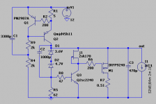
Mod2: Q1 lift via a 1000uF || 200R , and j2 replaced by a 2.4k resistor, as suggested in post 248 by jwb, that for him was measurably superior.
The test setup was as follows. The output of an HP201C sine wave generator in series with a 32V battery fed its output to the regulator. The sine wave value in volts is shown in the table as Vin, whereas Vout is the ripple at the output of the regulator. Both values are peak-to-peak, not RMS, visually measured on the oscilloscope.
Edit: forgot to mention that the load was a simple 400R resistor.
Mod0: circuit of post 214, no modifications
Mod1: J2 replaced by a 2.4k resistor
Mod2: Q1 lift via a 1000uF || 200R , and j2 replaced by a 2.4k resistor, as suggested in post 248 by jwb, that for him was measurably superior.
The test setup was as follows. The output of an HP201C sine wave generator in series with a 32V battery fed its output to the regulator. The sine wave value in volts is shown in the table as Vin, whereas Vout is the ripple at the output of the regulator. Both values are peak-to-peak, not RMS, visually measured on the oscilloscope.
Code:
Mod1
Freq    Vin    Vout    20*log(Vout/Vin)
120     8      1m      -78.0618
1k      8      1.9m    -72.4867
5k      8      2m      -72.0412
10k     8      2m      -72.0412
20k     4      2m      -66.0206

Mod0
Freq    Vin    Vout    20*log(Vout/Vin)
120     8      < 0.5m  < -84.0824
1k      8      1.8m    -72.9563
5k      8      2.2m    -71.2133
10k     8      2.5m    -70.103
20k     4      2.5m    -64.0824

Mod2
Freq    Vin    Vout    20*log(Vout/Vin)
120     8      1m      -78.0618
1k      8      3.5m    -67.1804
5k      8      2.9m    -68.8138
10k     8      2m      -72.0412
20k     4      2m      -66.0206
Edit: forgot to mention that the load was a simple 400R resistor.
Hi JWB,
Looking good - is there a way to easily trim the O/P voltage perhaps 5 - 10% as this is often better for the simple ccts like 2sk170/2sj74 buffers for trimming out DC offset and bias adjustments - R5 maybe?
Ikoflexer
The earthing connection is becoming a noisy "reference" everywhere, unfortunately. I'm currently trying out the centretap isolation transformer idea (so called balanced ac supply) for line noise reduction and connecting the centre tap to an earth stake outside the window to clean up the ground line.
I saw recently that John K of EC Designs has developed a version of line isolation called Charge Transfer Supply (see post2804 in the "Ultimate 1541a DAC" thread on this site, and a balanced version on post 2579) Sorry I can't add the direct links - worth a look.
A nice reg that sounds rather good.
Oops, just realized I made a mistake when replacing the resistor back with J2, I soldered J2 with D and GS reversed. Here are the numbers with J2 in place soldered correctly, for the circuit with no modifications.
Hence, I am still of the opinion that J2 should not be replaced by a resistor. Yes, the improvement is not that spiketacular all across the frequency spectrum but it's still an improvement.
jh, thanks for pointing out that thread, I'll have a look. I've been thinking for some time about some solution to get a cleaner earth reference. The fact that my window is 60ft above ground complicates matters somewhat. Which regulator are you saying sounds rather good? -- I'm always game to try another one.
Edit: while at it, why not replace the mosfet M1 with a 2N2905A, I thought to myself. So I did, and here are the results, let's call this Mod3. Note that the 2N2905A should have an adequate heat sink.
Code:
Mod0
Freq    Vin    Vout    20*log(Vout/Vin)
120     8      < 0.5m  < -84.0824
500     8      0.9m    -78.9769
1k      8      1.0m    -78.0618
5k      8      1.3m    -75.7829
10k     8      1.5m    -74.54
15k     8      2.0m    -72.0412
20k     8      2.0m    -72.0412
Hence, I am still of the opinion that J2 should not be replaced by a resistor. Yes, the improvement is not that spiketacular all across the frequency spectrum
but it's still an improvement.jh, thanks for pointing out that thread, I'll have a look. I've been thinking for some time about some solution to get a cleaner earth reference. The fact that my window is 60ft above ground complicates matters somewhat. Which regulator are you saying sounds rather good? -- I'm always game to try another one.
Edit: while at it, why not replace the mosfet M1 with a 2N2905A, I thought to myself. So I did, and here are the results, let's call this Mod3. Note that the 2N2905A should have an adequate heat sink.
Code:
Mod3
Freq    Vin    Vout    20*log(Vout/Vin)
120     8      < 0.5m  < -84.0824
500     8      0.7m    -81.1598
1k      8      0.8m    -80
5k      8      0.9m    -78.9769
10k     8      1.0m    -78.0618
15k     8      1.0m    -78.1618
20k 8 1.1m -77.2339Finally, if R1 is 0R, i.e. if we just remove the base resistor on the 2n2905a there is a further improvement and all outputs are below 0.9mV peak-to-peak ripple, when the input is 30V DC over imposed with a 8V p-p sine wave.
jwb, no problem. This answers some of my questions, and hopefully others' too. I wish I had better measuring equipment (don't we all). I'll probably put together some sort of active pumping load next, and see what that does.
jwb, no problem. This answers some of my questions, and hopefully others' too. I wish I had better measuring equipment (don't we all). I'll probably put together some sort of active pumping load next, and see what that does.
ikoflexer said:Craig, your comments are appreciated; they suggest a complete overhaul of the regulator which is beyond me. I am not dismissing your comments, just
This is design is due to salas, and my opinion, as a parenthesis, is that he's talented and also a very nice guy, (A lot of people around here can learn a lot from his attitude.) His design might not be the most technically correct but has some significant good things going for it; the following comments are b................snip........................................ * SOUND GOOD! OK, I have no idea and could find nothing relevant (even few speculate) on this topic. What factors are responsible for a good sounding regulator? Maybe it's simple, please enlighten me if you know.
* Not so important, but nice to have nonetheless, be easy to modify for high voltage (e.g. 150V).
Apologies for the bandwidth used to all that such comments are old news.
Cheers!
ikoflexer, no need to explain.
You asked me for comments on improvements to the existing circuit which I gave.
Glad to see reward come from your work.
Ah Ikoflexor,
I put together a rough variation of Salas's original unit - similar to #255 but with 9610, not the big fets - It works pretty hard driving my headamp (30V @ 250mA) but sounds rather good indeed.
I do feed it via a Simple Series reg (ZenMod's) after a standard Simple Cmultiplier (note the "simple" bit!).
When I used the same supply with the early version of the Toole shunt, it didn't sound nearly as good (note here, IMO) - the transients were better controlled, butmuch less detail and the balance of the sound seemed thin (on AKG 701 and Beyer 880s phones).
I'm waiting to see where the design finally ends up before doing another try, or perhaps a pcb, as it appears to be necessary for this not so simple regulator.
I do like JWBs cct as post #248 or #283 and will try this, but not sure about neg rail version and if there is provision for slight rail voltage trimming (avoids using servos, etc).
Could I ask if either of you find some spare time in your busy schedules to knock up a -ve cct for +/-15Volts @250mA for the "perfboard plumber"! [supply is +/- 28V after Cmx @ 1A - have the 9610/610s and also the H44/45s]
Going to try it out on the extraordinary Taylored DOA headamp (an EUVL project)
- Status
- This old topic is closed. If you want to reopen this topic, contact a moderator using the "Report Post" button.
- Home
- Amplifiers
- Power Supplies
- Best low noise regulator?