I've scavenged a BUNCH of excellent parts from a projection TV, and also some parts from CRT TV's, and I want to build a powerful SMPS for an audio amplifier to replace the need for a 1000VA mains toroid.
Output will be 30-0-30V, & high current for my low impedance speaker configuration. I can set my output voltage where I want, so I'm not majorly concerned with that.
The SMPS transformer I scavenged from the TV is HUGE, biggest I've seen yet in anything, so it should be perfect for an amplifier. It even has 2 center tapped secondary windings and also 2 non tapped windings. The primary winding is also center tapped, but the center lead is cut off. ALL the windings are really thick litz wire, so it should handle the current with ease.
Its original use in the TV was a single mosfet driving the primary from 320V DC, and it appeared to be self oscillating.
I wanted to do it differently with the parts provided, but using a PWM TL594 to drive it for simplicity. I didn't want to use a transformer from the IC to drive the mosfet, but wanted to drive the gate directly from the IC in some form, and provide my own 12V DC source for the IC chip.
Will this work for the primary side?
Attachments
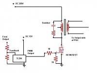
The original circuit had a snubber, that's why I used that idea. It was 100 ohm/1nf
The outputs were +/- 50V, 150V, and +/-20V and 6V, 10V, but I can adjust pulse width to lower it if it's too high. The biggest coils with thickest wire would be the one's I'd use (the +/-50V)
The Mosfet (it tests OK) is 800V, (STW18NK80Z)
I forgot to put it in the schematic, but I would have a reverse-biased diode from Drain to Source. That's what was in the original circuit.
I could also put a resistor in the source leg, and monitor current there.
sawreyrw said:You need to, at least, have some idea of what the transformer was originally used for. 320 volts without any snubber or clamp is pretty bold. What is the IGBT voltage rating?
The transformer was originally used for a SMPS projection TV power supply, and it used a MOSFET, not an IGBT.
It's all in my first post.
Power Factor Correction (PFC)
Hi everyone,
I want to design a SMPS with PFC. I am going to use the LT1248 power factor controller.Any suggestion for the type of rectifier used in the Boost converter?
This are the specifications:
Input voltage=240Vrms
Supply frequency=50Hz
Boost output voltage= 385V
SMPS output voltage=12Vdc
SMPS output power= 500Watt
Thanks,
bseokyew
@ EWorkshop1708:
The SMPS topology used in TV is mostly the Flyback converter, which corresponds to your posted drawing, and is commonly used only for power transfers below 300W. And I doubt that the used transformer in that design can be abused for a power supply with much higher power rating. The material selection is important and also the core size besides many other parameters and chosen topology (depending on the topology it either needs an air gap or not, derived from the circumstance at what point (in time) the energy is transfered from the primary to the secondary side).
@ bseokyew:
With an input voltage of 240Vrms the intermediate rail voltage should be chosen to at least 400V or even 420V (that's the reason why you can find 450V bulk capacitors). The boost converter should have an overhead of at least 20V (or even more) above the rectified main voltage plus tolerance (i.e. +10%, resulting in 244Vrms and therefore approx. 373Vpeak) for proper operation. For more information you should study carefully various application notes and/or datasheets of appropiate PFC-controllers. A good help (to start) might be the following link (this might help EWorkshop1708 too):
http://www.smps.us/smpsdesign.html
So maybe it's better to make a single ended SMPS instead....
I'm still confident I could get over 300W from this transformer. I've used transformers half this size at over 300W. The internal DC resistance is so low, my multimeter can't get an ohms reading other than flat 0 on ANY of the transformer coils.
My goal is the offline SMPS, but even if I made another 12V SMPS, this transformer would do great I'm sure. You can use them for step-up or step down, and operate properly at switching frequencies without complication. That's why I like to re-use the SMPS transformers. Much easier than having to make a toroid.
@ EWorkshop1708:
Well, you mentioned that the discovered transformer is huge, but this size could be irritating and could mislead you to totally wrong maximum power capability.
It would be (very) important to find out more about the material the core is made of. This, in connection with the chosen switching frequency, determines the maximum capability of the transformer. Basically the higher the frequency the higher the power transfer. However the maximum possible working frequency is given by the core material - otherwise the core losses will rise, which just means that the temperature could (or better: will extremely) rise.
The B-H curve determines the maximum magnetizing current which will lead to the necessary number of windings for the primary coil. Most common is a value of up to 300mT, but that all depends as I already mentioned.
Look out for any printed letters/numbers on the core. If you find something like i.e. "N48" or similar on it would be fine. If in doubt post some pictures of the core and in addition the dimensions.
If you like you can keep going with your trial-and-error method but I would recommend a more mathematically based method for your SMPS 'designs' - if someone else likes to call it still 'design' though. It may fail at certain load conditions and very likely at the max. power output.
Hi E - folks,
Myself an hobby electronics, maki'g toys from scrap motors n etc.
From past 6 months I'm trying to develop some HB led ligts. Now I need to have a Power supply which can drive the LEDs from 220V AC mains.
I am trying to devlope some cheeapest smps for this purpose. I have downloded some app. notese of PWM ics, but I am not able to designe the Power Trasnformer for the voltage & current required.Can any one help me for the same Please.
I think you need to find the schematic for the circuit this transformer was used in. Knowing the topology that it was designed for would save a lot of time in your design effort. The frequency that it was used at would be a big help. Also, if it was intended for a flyback circuit as an example, it can't be changed to a foward topology. You will still need to determine the turns ratios for all the secondary windings with respect to the primary, as that information is not usually on a schematic.
Winding a line frequency toroid would be an interresting project as an alternative. Very relaxing, sort of like basket weavng.
Winding a line frequency toroid would be an interresting project as an alternative. Very relaxing, sort of like basket weavng
.- Status
- This old topic is closed. If you want to reopen this topic, contact a moderator using the "Report Post" button.
- Home
- Amplifiers
- Power Supplies
- Simple TL594/single MOSFET offline SMPS