Eva said:A boost converter should include cycle by cycle current limiting, otherwise it may destroy itself at startup or during load steps, particularly if it uses voltage control. Peak current control is preferable. If you want to go discrete, component count is going to end up being high.
Operating frequency, inductance and peak to peak ripple current are mutually related parameters. You usually fix two of them and calculate the third one. Formulas are easy to figure out if you assume steady state operation, and you can learn a lot by finding them out and drawing the waveforms.
Consider UC3842/UC3843/UC3844/UC3845 family (the latter is best suited to your application) as a compromise between a discrete solution and a fully integrated one.
Since this is a hard switched converter, you should learn about diode reverse recovery too, and about continous-conduction and discontinuous-conduction operating modes. Only Schottky and SiC diodes are free from reverse recovery phenomena.
EVA-
Referencing my earlier 12V-19V 2F booster using the SG3525, two MOSFETs and a double-diode, I wound my inductor bi-filar, in auto-former fashion. Several of these units worked well, others for a while then they die. Blown MOSFETs, Fried Diodes, and partially melted windings on the toroid. My question is this: What is the best material to use for the boost inductor? I have tried both ferrites and powdered-irons, and gotten much better results with the irons. Presently, I am using T-106-26 toroid (the BIG core from an AT/ATX supply). Like I said, some units run fine, and others fail. pc boards were done at a prototype house (ExpressPCB), frequency is 145kHz (osc), and 72.5kHz (switching). Calculated inductance called for, is 100mH, and the Amidon datasheets calls for 33-34T on a T-106 of the #26 material. Is there a better mix powdered-iron I should be using? Since both inductors are wound on the same core, should the 100mH be 200 mH? 50m H? HELP!
Thanks,
Steve
Hi, since the boost converter inductor current is (in CCM) continuous, there will be a certain DC flux bias within the core. Select a material that has high saturation flux density. Then do some rough calculations to find out the core losses as well as copper losses. A material with high permeability means less turns.
Do you really mean that you are using 100 mH (milli-henry) inductors @ 75 kHz? Sounds way too much! What are the current levels in your design? Finding out the value for a boost inductor is quite easy, help will be available is requested.
Cheers,
Do you really mean that you are using 100 mH (milli-henry) inductors @ 75 kHz? Sounds way too much! What are the current levels in your design? Finding out the value for a boost inductor is quite easy, help will be available is requested.
Cheers,
Hi, that's what I though it to be. In SI system the prefix "milli" is abbreviated as 'm', whereas "micro" is like you said the greek letter. Since our keyboards (mine at least) do not support greek letters, micro is very often denoted with 'u'. So that 100 microhenrys of yours would be written 100 uH.
This can be most confusing sometimes. It's just the lack of standards that make our lives miserable!
This can be most confusing sometimes. It's just the lack of standards that make our lives miserable!
Sponkii said:Hey..
I have some interest in building a boost converter.
My demands are following:
Input voltage 13-14.5V DC
Output voltage 19 at 5A. i do not think that a small amount of ripple is a problem.
The but!
i have never had experience with boost converters before.
i have a couple of different coils and toroids that i hope i can use.
i had an idea of using something like 80khz to drive, but i have seen in other forums that you use around 50khz in SMPS?...
what would you recommend?..
I have enclosed a design idea.
- made something like that on breadboard, but uses voltage reg on input (which get hot), it outputs from Vin-0.5 to 27.8V the transistor is BUZ20, cant remember name of diode, but it should be fine, have also tested different coils.
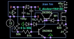
I noticed that your requirement of 17V @ 5A is pretty close to this 14V @ 8A circuit that I did in LTspice. The main adjustment is the .01ohm current sense resistor. Note that the circuit varies its frequency as part of the regulation process. The circuit could at least be a learning tool for SMPS operation. I'm not sure how the circuit will work in real life, though, I have made circuits based on its type of theory.
Attachments
- Status
- This old topic is closed. If you want to reopen this topic, contact a moderator using the "Report Post" button.
- Home
- Amplifiers
- Power Supplies
- Boost converter