Hello all. For some reason or another, I have learned a lot since I posted the topic below, about 6 months ago.
http://www.diyaudio.com/forums/showthread.php?postid=1551799#post1551799
The way I approach electronics is becoming more versatile, I am getting more clever and creative.
My learnings have dealt mainly with amplifier design, but there is little difference between a linear regulator and an amplifier. Both are interesting to design.
So my question was at first, "if we can get vanishingly low distortion in amplifiers using simple circuitry, why wouldn't be be able to do the same with a linear regulator?"
I do believe it's possible with discrete circuitry, which is one of the reasons I posted.
I understand that many of you do not usually put the time in to build regulators for your amps. Twenty 2200uF caps usually does the job, doesn't it!?
Sorry, even though most would be happy with just a thousand caps on the rails, with some filtering here and there, I absolutely HAD to do this.")
With clever design, we should not need caps (except for after the rectifier), even though they look cool. If you want it to look good, perhaps you should try replacing the zener with an LED. Tests on this forum have indicated that IR LED's are the best, though they don't emit light.
You may think I'm slightly insane, but I wanted to make a good regulator and for this to happen, traditional values must be reexamined for their value. We see this commonly in amplifier designs, especially before the "great awakening" of Doug Self and other such designers.
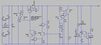
At any rate, Notice the transistors used. They were all chosen with Cjo in mind. This is essential to HF performance.
Q5 and Q6 form a Rush cascode, which works relatively well with regulators, based on my simulator experience. I am absolutely certain that if I used an ordinary LTP as the voltage sensor here I would be fried within seconds from RF oscillation.
Q9, Q7 and Q8 form a very nice CCS, and with the filtering cap this works quite well.
The MOSFET and attached circuitry is a diabolical testing device to prove the supply's strength. This is very unethical I might add. It generates a VERY FAST negative pulse after climbing to 1A. If C4 goes any lower than 10nF, the circuit begins to oscillate. Some over-voltage protection might help calm oscillations.
It helps reveal the finer details of operation in a supply. This idea was put forth by Mr. Mooly, whom I must give credit.
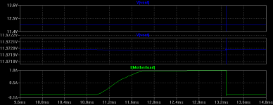
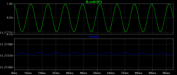
Regulation is EXTREME for this circuit, I'll just hope it will work in real life.
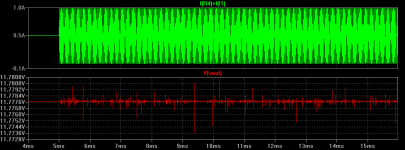
Apart from the spikes generated, you'll see that the output voltage varies almost imperceptibly from 0-1A. The sim won't let me zoom in any more. If I could guess, somewhere around 20-30uV. And this stays the same across the entire audio band.
Naturally, criticism and suggestions are encouraged as I posted this primarily so that I might learn more through them.
I will post simulation results right after this. Attacxhed is the schematic.
- keantoken
http://www.diyaudio.com/forums/showthread.php?postid=1551799#post1551799
The way I approach electronics is becoming more versatile, I am getting more clever and creative.
My learnings have dealt mainly with amplifier design, but there is little difference between a linear regulator and an amplifier. Both are interesting to design.
So my question was at first, "if we can get vanishingly low distortion in amplifiers using simple circuitry, why wouldn't be be able to do the same with a linear regulator?"
I do believe it's possible with discrete circuitry, which is one of the reasons I posted.
I understand that many of you do not usually put the time in to build regulators for your amps. Twenty 2200uF caps usually does the job, doesn't it!?
Sorry, even though most would be happy with just a thousand caps on the rails, with some filtering here and there, I absolutely HAD to do this.
With clever design, we should not need caps (except for after the rectifier), even though they look cool. If you want it to look good, perhaps you should try replacing the zener with an LED. Tests on this forum have indicated that IR LED's are the best, though they don't emit light.
You may think I'm slightly insane, but I wanted to make a good regulator and for this to happen, traditional values must be reexamined for their value. We see this commonly in amplifier designs, especially before the "great awakening" of Doug Self and other such designers.
At any rate, Notice the transistors used. They were all chosen with Cjo in mind. This is essential to HF performance.
Q5 and Q6 form a Rush cascode, which works relatively well with regulators, based on my simulator experience. I am absolutely certain that if I used an ordinary LTP as the voltage sensor here I would be fried within seconds from RF oscillation.
Q9, Q7 and Q8 form a very nice CCS, and with the filtering cap this works quite well.
The MOSFET and attached circuitry is a diabolical testing device to prove the supply's strength. This is very unethical I might add. It generates a VERY FAST negative pulse after climbing to 1A. If C4 goes any lower than 10nF, the circuit begins to oscillate. Some over-voltage protection might help calm oscillations.
It helps reveal the finer details of operation in a supply. This idea was put forth by Mr. Mooly, whom I must give credit.
Regulation is EXTREME for this circuit, I'll just hope it will work in real life.
Apart from the spikes generated, you'll see that the output voltage varies almost imperceptibly from 0-1A. The sim won't let me zoom in any more. If I could guess, somewhere around 20-30uV. And this stays the same across the entire audio band.
Naturally, criticism and suggestions are encouraged as I posted this primarily so that I might learn more through them.
I will post simulation results right after this. Attacxhed is the schematic.
- keantoken
Attachments
Ah, here's something interesting.
See the strangeness? This happens because of R8. When the output current goes lower than about 1mA, Q4 begins to shut off, which reduces the overall gain of the darlington pair, which reduces open-loop gain, increasing error. Regulators are no different than amplifiers.
Putting a 1.2k resistor across the rails improves operation by providing bias current. This is wasteful, however. Removing R8 altogether does not help.
Multiple 2SC's can be paralleled to provide more output power, as one can only handle about 1A. It is important to use a pass transistor with low Cjo, like the 2SC4793 here. If you don't, it will surely oscillate.
- keantoken
Attachments
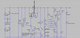
Well, whatever. Lowered supply voltage, we certainly don't need 36V.
An interesting tidbit here:
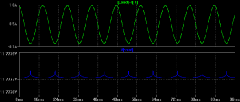
At high frequencies, the Cjc of Q10 became a problem. For those of you who simulate this you will see the cause and effect if you look at Q10's emitter current and the output voltage.
This fix is to use a 100-ohm resistor on Q10's collector. This causes Q10's collector capacitance to not just be a short to ground.
The result, is no funny glitches in the output at 40KHz, and more stability.
I have seen people put diodes in the position the 100-ohm resistor now is, though I don't know if that solution was for the same problem.
Also, temperature compensation. However, due to the diodes' constant-voltage effects, this lowers the ability for regulation. I don't think temperature stability is that important, really, so I don't think it's necessary. Maybe it should be a switch option.
Also used Christer's models for the output transistor, not sure if it's better or worse than the ONSemi model, but the circuit works just as well with both.
I will gladly receive any kind of criticism or advice, even if you tell me that I'm a failure and I should go jump off a cliff. Or if you tell me it doesn't work, etc. It gets scary when no one's around...
- keantoken
An interesting tidbit here:
At high frequencies, the Cjc of Q10 became a problem. For those of you who simulate this
you will see the cause and effect if you look at Q10's emitter current and the output voltage. This fix is to use a 100-ohm resistor on Q10's collector. This causes Q10's collector capacitance to not just be a short to ground.
The result, is no funny glitches in the output at 40KHz, and more stability.
I have seen people put diodes in the position the 100-ohm resistor now is, though I don't know if that solution was for the same problem.
Also, temperature compensation. However, due to the diodes' constant-voltage effects, this lowers the ability for regulation. I don't think temperature stability is that important, really, so I don't think it's necessary. Maybe it should be a switch option.
Also used Christer's models for the output transistor, not sure if it's better or worse than the ONSemi model, but the circuit works just as well with both.
I will gladly receive any kind of criticism or advice, even if you tell me that I'm a failure and I should go jump off a cliff. Or if you tell me it doesn't work, etc. It gets scary when no one's around...
- keantoken
Attachments
Attachments

Keantoken,
Here's a little feedback.
You could replace all of the transistors and resistors associated with the zener biasing with a single resistor, because the current through the zener will be almost constant anyway.
I don't know what you mean by Cjo. The most important SPICE transistor parameter for frequency response is Tf, the forward transit time. Tf=1/(2*pi*fT). fT is the frequency where the magnitude of the current gain reaches 1. Note that this is an approximation that neglects the base to collector (Miller) capacitance. The SPICE BJT model is a form of the hybrid pi model. Do a little research on this. http://www.intusoft.com/lit/WkwModels.pdf is a excellent reference on modelling.
Your voltage regulation loop is interesting, but I would use a differential amplifier. This will provide better temperature stability, and probably would need fewer transistors.
You should use a higher bias current through the zener. You don't want the zener operating on it's knee. A 5.1 volt zener has the lowest temperature coefficient. This is the crossover point between a negative and positive TC.
Rick
Thank you.
Lower Cjo transistors are more stable in high-OLG places, and have less of a tendency to oscillate.
Besides, I've noticed that low Cjo transistors usually have high transition frequencies as well.
I don't know if you're suggesting I use an opamp, but Q5 and Q6 are a diff. amp. It has a voltage gain of about 8, where the input is the voltage between the two bases and the output is the voltage from collector to collector. This is called the Rush cascode, and it has specific benefits over the LTP.
I am not worried so much about temperature stability, although I don't know how much it is prone to wander in real life.
I will look at that modeling book, but that thing is HUGE and I will need time. I am curious about how I might tweak models to fit the datasheet curves better.
- keantoken
Anyways, I've had much trouble getting anything to keep from oscillating if I used transistors with too much Cje.
This might actually have something to do with simulator settings. I've recently discovered that if I set the maximum timestep to a lower value, the oscillations go away!
So this circuit is actually more stable than the simulator is showing it to be.
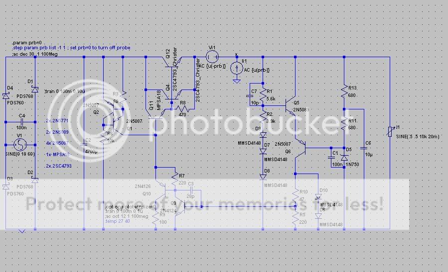
Recently I learned about this thing called a miller compensation cap, which also increased stability. I also replaced the CCS on the zener with a bootstrap.
D10 and D6 form a protection circuit for Q3, as large load spikes will cause Massive currents to flow through Q3's base otherwise. The Rush cascode is an amazingly fast device!
Here is the schematic:
- keantoken
This might actually have something to do with simulator settings. I've recently discovered that if I set the maximum timestep to a lower value, the oscillations go away!
So this circuit is actually more stable than the simulator is showing it to be.
Recently I learned about this thing called a miller compensation cap, which also increased stability. I also replaced the CCS on the zener with a bootstrap.
D10 and D6 form a protection circuit for Q3, as large load spikes will cause Massive currents to flow through Q3's base otherwise. The Rush cascode is an amazingly fast device!
Here is the schematic:
- keantoken
- Status
- This old topic is closed. If you want to reopen this topic, contact a moderator using the "Report Post" button.
- Home
- Amplifiers
- Power Supplies
- Another Linear Pass Regulator