The difference in voltage you specify renders the boost topology unusable. The duty cycles involved become to small to achieve a reasonable inductor design and control loop stability.
Have a look at push-pull, full bridge or half bridge topologies with a transformer.
There are inverter designs on the web that do more or less what you need.
Have a look at push-pull, full bridge or half bridge topologies with a transformer.
There are inverter designs on the web that do more or less what you need.
Boost converters are practical only when the ratio between output and input voltage is not too high, say 4:1 maximum. They become progressively inefficient as the ratio increases above that.
For higher ratios a transformer coupled converter is required. The usual approach when only 12V or 24V are available is an unregulated push-pull (very few inverters use regulation).
You could use a boost converter if you had banks of series-connected batteries, like in big UPS systems, producing something like 120V DC to start with.
On the other hand, consider that when they talk about "boosting a voltage" they may not actually have a "boost" topology converter in mind.
did u mean "350V is not const. all the time" by unregulated push-pull ???
Then it will change from 470V dc to 350V dc as the battery voltage decreases (13.5V-10V).
Eva, Can u tell me what most of the manufacturer do in battery boost stage to make sine wave inverter?
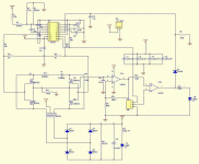
I have already made a push pull arrangement for making 350V dc with feedback (using 40khz SG3525). If I use no feedback(i.e. duty cycle is 95%) then everything is fine. the FET isn't blowing and body heat is as normal as possible. Also I am getting clean wave across the transfrmr. But when i use feedback(i.e. duty cycle is other than 95%) the voltage across the trsnsfrmr isn't stable (as seen from the oscilloscope), and body heat is as much much higher as it sometimes FET is blowing even i use big heatsink.
I am attaching here the diagram........
Attachments
do not drain your battery to 10v, you will loose it sooner then you expect, may be 11.5v is batter so 11.5v to 12.5v = 35v volt drop on the secondary, and the battery is happier then before. probably your feedback is responding very fast, slow it down would help, lower the gain and do some compensation to slow it down, inverter stuff dont really need too tight regulation,
also current sense seems impractical, use pair of current sense transformer,
http://www.diyaudio.com/forums/showthread.php?postid=730561#post730561
also current sense seems impractical, use pair of current sense transformer,
http://www.diyaudio.com/forums/showthread.php?postid=730561#post730561
- Status
- This old topic is closed. If you want to reopen this topic, contact a moderator using the "Report Post" button.

