The first limiting factor is chip heating. The second one is switching times.
Do some research on MOSFET/IGBT gate charge and the calculations related.
The amount of heat produced inside the IR2110 will depend on supply voltage, operating frequency and total gate charge. Switching times are directly related to gate charge too.
The datasheet contains plots of chip temperature increase versus operating frequency for various reference MOSFET models.
As an alternative, have a look at some of the Micrel devices. They are usually not as fast as the IR parts, but some models can deliver a quite high gate current. That would allow you to drive some more parallel fets.
Micrel Gate Drivers
Micrel Gate Drivers
You don't need to use both necessarily.
Using the IR2110 shutdown will give you an almost immediate response, and is very good for instantaneous over-current protections for example. However, if you release the shutdown, the IR2110 does not control the switch-on of the converter as a whole.
The SG3525 shutdown may be a bit slower, but just a bit. When the shutdown condition is removed, the SG3525 will come back "more clean" than the IR2110.
Of course, it depends on how you intend to use the shutdown, I recommend you just pull the IR2110 shutdown to ground and only use the SG.
The tricky bit is the risk of an "intermediate" switch-on of the High side driver. If you have been unable to switch the low side on first, you may end up with insufficient energy in the bootstrap supply. The high side driver is then not able to achieve full saturation in the mosfet.
My application was a synchronous rectified boost, and the intermediate failure led to a reversed current in the switching node, killing the two mosfets and the gate driver. The solution was to force the driver to switch on the low side first, allowing the bootstrap to charge up before switching the high side.
My application was a synchronous rectified boost, and the intermediate failure led to a reversed current in the switching node, killing the two mosfets and the gate driver. The solution was to force the driver to switch on the low side first, allowing the bootstrap to charge up before switching the high side.
Re: SMPS picture
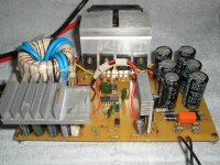
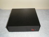
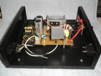
How is that transformer setup? Is that blue wire your secondary? How many turns? It's a very nice looking supply, and I like the CPU fan for your power devices!
CHACALPOWERS said:Hi SMPS builders
This is my SMPS. 13.8V, 75A, Only 0.1V of voltage fall.
Thanks for all.
Sandro.
How is that transformer setup? Is that blue wire your secondary? How many turns? It's a very nice looking supply, and I like the CPU fan for your power devices!
Mr. EWorkshop1708
Hi Mr. EWorkshop1708
Thank you very much. I'm so happy with your comments, ok?
There is two 2 in. outer diameter toroid cores one up other. 19 turns primary winding and 3 + 3 turns secondary winding (blue wire). I like it. It's so strong, no voltage fall in my power test with 0.18 Ohms resistor (76.6A).
About the cooler in the heat sink I think it's no necessary because the IRFP460 stay "ice", only the diodes heatsink stay warm.
REgards
Sandro
") )
) 
DC-DC 12V/35+35V
Hello Friends
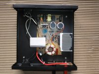
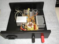
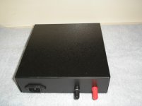
Here is anothers SMPS
http://i186.photobucket.com/albums/x186/chacalpowers/AGILENTreadcpia2.jpg
http://i186.photobucket.com/albums/x186/chacalpowers/AGILENTreadcpia2.jpg
http://i186.photobucket.com/albums/x186/chacalpowers/agilentREADcpia.jpg
http://i186.photobucket.com/albums/x186/chacalpowers/DCDC.jpg
http://i186.photobucket.com/albums/x186/chacalpowers/SMPS40A2.jpg
http://i186.photobucket.com/albums/x186/chacalpowers/SMPS40A3.jpg
Your comments are always wellcome.
Regards
Sandro from Brazil.
Hello Friends
Here is anothers SMPS
http://i186.photobucket.com/albums/x186/chacalpowers/AGILENTreadcpia2.jpg
http://i186.photobucket.com/albums/x186/chacalpowers/AGILENTreadcpia2.jpg
http://i186.photobucket.com/albums/x186/chacalpowers/agilentREADcpia.jpg
http://i186.photobucket.com/albums/x186/chacalpowers/DCDC.jpg
http://i186.photobucket.com/albums/x186/chacalpowers/SMPS40A2.jpg
http://i186.photobucket.com/albums/x186/chacalpowers/SMPS40A3.jpg
Your comments are always wellcome.
Regards
Sandro from Brazil.
- Status
- This old topic is closed. If you want to reopen this topic, contact a moderator using the "Report Post" button.
- Home
- Amplifiers
- Power Supplies
- IR2110 question (help me)