")
HF interferences are very difficult to remove, because of it propagates also by radiation. The best is to filter it, as much as possible, and as close as possible to the rectifier - preferably right after the rectifier and physically very close to it. HF LCLC is a good option.
Also, it is beneficial to consider metal shielding to the PSU, including the power inlet, the power transformer(s), the rectifier(s) and the initial filtering (both mains frequency and HF). When metal shielding is used, it may be beneficial to have HF CLC inside the shielding and another CLC, or LC, outside the shielding, adjacent to it.
In any case, for all kinds of interferences, it is much better to filter them before the SSHV2, not after it.
From the power supply side - nothing, but you may find some signal scraps on the B+ line.how many ripple add
You have already made the right decision before - why you decided to change it?merlin el mago said:I want to remove HF.
...
I used RC filter before the SSHV2 in other PSU and remove a lot of HF so SSHV2 don't remove all HF.
What can "add ripple"?When I said how many ripple adds is for the load.
- There could be (theoretically) "amplifying" of the power supply ripples. In case of SSHV it is not the case.
- There could be some rippling caused by changing current due to the powered circuit work. The amount of the disturbances depends on many factors and can't be estimated without simulating (modelling) the whole system.
Sorry, tried to understand but failed. Maybe the native speaking people can help?Because in the new PSU for other project can use RC 1ohm 3uF because the SSHV2 can run with more than 1V of input ripple.
My start for removing HF noice would be a small, 10 nF or so 1000 V poly or silver mica right after the rectifiers. Even more effective would be to use (C)-L-C choke input and start with the 10 nF. In practice it would act like choke input (DC=0,9xAC). Very effective also for HF
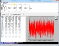
In my PSUDII simulation the last RC 1 ohm 3uF just before the load increase the ripple.
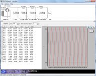
Circuit is oscillating. Increase last R from 1 to 10 Ohm
But really. Trying to combine DHTRobs passive filter layout with active filtering changes the whole idea. I think you should ditch that. Putting resistance after the shunt just puts their good job in the closit. Short twisted wires directly as close to the load as possible from shunts, nothing inbetween. If HF noice/trancients is a problem, try decoupling near bridge.
Last edited:
Just change the sensing resistor to 1 Ohm now. Looks like it will push the borderline just so that may prove a good help.
Right, so got this now sorted and is working like a charm. Increased raw supply to allow output voltage increase but small drop in the CCS, changed CCS FET and added bigger heatsinks to minimise temperature drift at maximum current. To run this regulator at 85-90mA you need them clearly! Thanks for the tips
See further notes here: Adjusting the shunt regulator | Bartola Valves
cheers,
Ale
My start for removing HF noice would be a small, 10 nF or so 1000 V poly or silver mica right after the rectifiers. Even more effective would be to use (C)-L-C choke input and start with the 10 nF. In practice it would act like choke input (DC=0,9xAC). Very effective also for HF
Can't do it because I need B+ before SSHV2 minimum 300VDC
Circuit is oscillating. Increase last R from 1 to 10 Ohm
But really. Trying to combine DHTRobs passive filter layout with active filtering changes the whole idea. I think you should ditch that. Putting resistance after the shunt just puts their good job in the closit. Short twisted wires directly as close to the load as possible from shunts, nothing inbetween. If HF noice/trancients is a problem, try decoupling near bridge.
If I increase resistor value change the filter value
Sims 1 and 10 ohms for visualisations
Also you reduce ripple if you increase the value of last capacitor but the same problem like resistor = value of filter will change
Right, so got this now sorted and is working like a charm. Increased raw supply to allow output voltage increase but small drop in the CCS, changed CCS FET and added bigger heatsinks to minimise temperature drift at maximum current. To run this regulator at 85-90mA you need them clearly! Thanks for the tips
See further notes here: Adjusting the shunt regulator | Bartola Valves
cheers,
Ale
Happy end then. And a nice documentation of the proper utilization moves. Congrats.

Because in other PSU for other load I compared with or without filter and my ears prefered with filter.
This in itself is no evidence for the presence of HF noise. It may stem from various reasons.
- Home
- Amplifiers
- Power Supplies
- Simplistic MosFET HV Shunt Regs