Long distances defeat the main advantage of regulated supplies, namely low output impedance.
Long distances must have high impedance.
To get the benefit of regulated supplies the regulator should be right next to the client circuit.
The higher the current slew rates the worse this problem becomes.
At very high current slew rates, using regulators on long distance leadouts is a waste of resources.
Remote sensing does not solve long distance powering.
Completely agree is not sense to make a very good regulator and place it long distance from load.
Guys, I don't need to be convinced of the technical benefits, because to me it makes sense. If you look back I was the one pushing for sense/force wires in the old days when we extended the low impedance of v1.0 (low voltage) by adding the extra bjt source follower. I was just wondering if anyone could hear the difference, that's all.
Edit: basically I'd just like to know for myself, out of simple curiousity. Anecdotal evidence would be enough for me.
Edit: basically I'd just like to know for myself, out of simple curiousity. Anecdotal evidence would be enough for me.
Kazuo san got rather impressed of what 4 wires could do for his burgeoning Reflektor experiments although he was not convinced due to short distance and was using 2 wires at start. I could feel it was worthwhile in most applications too. Both in low V and high V. 4 wires connection can be more prone to EMI is one danger and if without a scope some perceived harshness is tell tale. It can almost always be remedied if it happens by proper wiring dressing and/or some extra sense loop decoupling at the reg. People can subjectively check 4 VS 2 wire on their own application by shorting F+ to S+ and F0 to S0 locally at the reg connector with short jumpers and do A to B critical listening so to respond back to your anecdotal statistical query. No use of the soldering iron is needed if 4 wire mode is already there. The local shorting will effectively make it into 2 wire for the curious to evaluate.
Hey guy's I'm new to the sshv2 I was wondering when setting it up are you guys using the ma needed in the formula to calculate the resistor value? Here's what I mean, I need 19ma w/ the drop off of 20ma that equals 39ma. So, 310v/.39ma = 793 ohm so a 800 ohm resistor or is it 310/.19 = 1631 a 1.6k ohm resistor.
Could someone let me know, Thanks!
Could someone let me know, Thanks!
") will do!
will do!Mosfet ripple filter
HI.
I built a 572b amp the out put transformer was so big could not fit a choke to the box.
Does not have any hum even on 100+db horns but I would like to fit a mosfet regulator/ ripple filter.just for the driver tubes about 40-50 ma
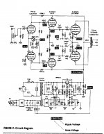
I found the circuit for a mosfet ripple filter in AudioXpress Jan 2001 for a 3cx300 amp. circuit attached.
3cx300 amp runs at 450 volts about 240ma; mosfet only drops a few volts. i have 630 volts.
Do you think this circuit would handle 630 volts at 60ma; I have a irfc60 and some 200 volts 5 watt zeners. Would any one have a pcb for this circuit?
Thanks
Phil
HI.
I built a 572b amp the out put transformer was so big could not fit a choke to the box.
Does not have any hum even on 100+db horns but I would like to fit a mosfet regulator/ ripple filter.just for the driver tubes about 40-50 ma
I found the circuit for a mosfet ripple filter in AudioXpress Jan 2001 for a 3cx300 amp. circuit attached.
3cx300 amp runs at 450 volts about 240ma; mosfet only drops a few volts. i have 630 volts.
Do you think this circuit would handle 630 volts at 60ma; I have a irfc60 and some 200 volts 5 watt zeners. Would any one have a pcb for this circuit?
Thanks
Phil
Attachments
- Home
- Amplifiers
- Power Supplies
- Simplistic MosFET HV Shunt Regs