Quote:
Originally Posted by nicoch58 View Post
info
Firefox marked the forum as an "Attack site".
Hey, thanks for providing this information. It helps to know what's going on and I'm not the only one seeing this!
I still get the warning everytime I try to load the Diyaudio site...

And happily ignore it

Nice photos. When you blow there, yes its normal to drift. There is no ventilation there in your build, so help them Q4 Q5 out with sinking when able.
Yes, before using SSHV2, there is not much heat in the box....now I think I will try and mount the power transformer, and the caps with spacers, leaving a gap so there could be circulation.....( the back is never fully enclosed ).....
Seasons Greetings.
I am still struggling with this vari-mu compressor build - mainly it's stability. And after many hours of trying to debug I started to play around with the SSHV2 boards I have and I came into all sorts of trouble.
With the unit in true bypass, the reg boards seem to be injecting noise into the circuit somehow. This is solved by changing the current trim pot and output voltage trim pot, but I can now not get back to the original values.
I have been playing with it for most of the day now and have got to the point where I need to ask for help. The true bypass is a coax running from input to output ettectively, and the input side is grounded at one end. So are my regs injecting noise into the ground and that is being picked up by the cable?
I have tried a couple of combinations of transformers I have, the one I am using is rated at 100mA and I am not using near that, and it is not getting hot so I am assuming that it is OK.
So maybe my boards are oscillating or maybe I have implimented them wrongly to cause oscillation... Could someone suggest whether that is correct and how I might solve it?
Thanks for any advice.
Charlie
Both regs have been working fine up until now, I am pretty sure they are oscillating but do not know the cause. Especially the reason for it shunting noise to ground - this may be normal when oscillating - I do not know.
Thanks
What changed in the full circuitry, at what point they started acting up? Are all semis in the regs showing working voltages like VGS, VBE? Was there a certain incident or revision, or an active part likely to have changed behavior in the client? A rewiring? Have you actually seen AC waveforms riding the DC line on a scope? When oscillating weird things happen all over, so its not unlikely for oscillation actuallly happening. Are there any capacitors from rail to ground or series connected parts on the rail after the reg's output? If yes, what are they?
What changed in the full circuitry, at what point they started acting up? Are all semis in the regs showing working voltages like VGS, VBE? Was there a certain incident or revision, or an active part likely to have changed behavior in the client? A rewiring? Have you actually seen AC waveforms riding the DC line on a scope? When oscillating weird things happen all over, so its not unlikely for oscillation actuallly happening. Are there any capacitors from rail to ground or series connected parts on the rail after the reg's output? If yes, what are they?
Did some more testing this morning. Both regs work fine on thier own, but they go instable when running together. When both regs are running together I can not get anywhere near the voltage required for the circuit with the trim pots.
There is definite LF oscillation, when inputs are shorted there is large instability in the low end when reading a live trace. And there is a pulsing AC waveform on the DC rail. But this is not present when using one reg at a time.
The setup is;
CRC - individual RC per reg - SSHV2 - circuit. There are no filters after the regs just OPT and input stage anode load.
This is a new issue as I have been testing for a couple of weeks with no trouble at all, but after a break and coming back to it this has happened. I have not made any major changes to the ciruitry, only adjusting bias.
All transistors have working voltages. Is there anything else I can check?
Thanks
Hi Salas, wishes of happy new year.
I need your help if possible, yesterday working late and tired, I did a stupid mistake with one working SSHV2 board, I connected my meter probes set to measure on the 20A range, to the output of the board, wanting to measure voltage
Of course this produced a nice small flash on the terminals/probes, and the regulator stopped working. The led is still on, but now I get only around 6,4V on the output.
What I need is for you to tell me in your opinion what should be changed to avoid taking all transistors out.
Many thanks.
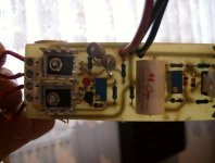
Hi i have build my salas, but i have another board, little smaller. But similiar to the org salas. When I have attached power suply R1 burned, when i mesure the R1 on the board it has 97R, when I measure R1 in another board it have 120R( i have two salas's) i have 280vdc power suply, my target is 260vdc, for now my dummy load is 17k(15mA in 260vdc)What is going on? please help me.A have add zip with the eagle files.
Attachments
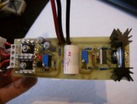
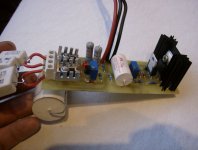
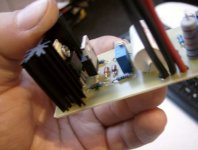
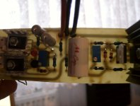
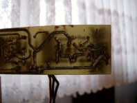
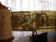
I have search for the bugs, but nothink found. So i add a pictures.
Attachments
- Home
- Amplifiers
- Power Supplies
- Simplistic MosFET HV Shunt Regs