What would be the best way to remove solder from a double sided board during repair??
Also, there are 2 different kinds of solder wick. Some have a small amount of flux to help activate the solder joint quicker under heat so the solder is absorbed faster to the wick. I prefer this type for sensitive joints, but in this application (SSHV2 PCB) you probably may not need it.
Why manual...when "automatic" is available for us lazy types??

Hey Roger57, Merry Xmas. Did you get the chance to audition your amps mods by now?
Hi Salas!
Merry Christmas to you in beautiful Greece!
I just completed the modifications today and have only listened for a couple of hours. So far, terrific! Recall I have 2 identical Class A amplifiers in passive bi-amp mode on my speakers. The amplifier I modified was the high frequency unit. I find the high frequencies have better resolution and linearity. Extremely nice placement and clarity of vocals. It did what I expected.
However, I ended up having to back off the total current being delivered by the screen regulator. Recall that I required 60mA to the screens at full power output. With the screen current being dynamic, and this unit the high frequency amplifier, I could afford to back the current down to keep the heat sink under 50C, in spite of it's size! I now have adjusted the total current at the test point for 65mA. So far in listening, I believe this will be adequate given the volume I listen at. There are 2 SSHV2 units and a filament regulator all bolted to the same heat sink, so there's a lot of dissipation happening there! I will need to increase the heat sink size on the low frequency amplifier as I will need all the screen current there. No problem as I have more of the same heat sink material and the room on the baseplate to install it. I'll take a couple of pictures later in the week when I have it back in to do some final small updates.
My best wishes to you for a great 2013, and thanks again for everything you do for all who are a part of these forums. It means a lot!
Gary
Last edited:
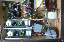
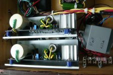
 ...thankyou for all the helps....I have finished changing Q4, Q5 and the 117 on the questionable board mentioned...I have also renew all the solder joints....I have also added small heat sink with fins to each of the Q4 &5....the 2 boards are now doing 279V in....30mA at TP, and 260V out, with 48V across the 6K loading resistors......they have been steady for more than an hour.....but the Q4 and 5 are still quite hot....and when I blow on them...the V out jumps to 265...it is normal like this??.....I am thinking of adding a piece of aluminum strip the the sink
 The photos show the two board installed (no sink yet seen with the Q4 & 5)
Attachments
IMO, these are the minimum size you should install on the 2 transistors (Q4,Q5)
274-2AB Wakefield Thermal Solutions | 345-1087-ND | DigiKey
274-2AB Wakefield Thermal Solutions | 345-1087-ND | DigiKey
Website Issues?
Salas,
I see you're a forum moderator. Are you aware of any website issues with DIY Audio? Whenever I try to post anything, (the last 3 tries anyhow) I get a warning page from Firefox / Google saying this is a reported "Attack" website.
Know anything about this?
Gary
Salas,
I see you're a forum moderator. Are you aware of any website issues with DIY Audio? Whenever I try to post anything, (the last 3 tries anyhow) I get a warning page from Firefox / Google saying this is a reported "Attack" website.
Know anything about this?
Gary
Last edited:
....and when I blow on them...the V out jumps to 265...it is normal like this??.....I am thinking of adding a piece of aluminum strip the the sink
The photos show the two board installed (no sink yet seen with the Q4 & 5)
Nice photos. When you blow there, yes its normal to drift. There is no ventilation there in your build, so help them Q4 Q5 out with sinking when able.
Hey, thanks for providing this information. It helps to know what's going on and I'm not the only one seeing this!
- Home
- Amplifiers
- Power Supplies
- Simplistic MosFET HV Shunt Regs