Salas,
....
I ran the regulator with 450V in for about 2 hours and there is no issues, and no noise or oscillation I also switched it on and off about 30 times, to 435V in, about where it will be operating, with no issues
...
Thanks for your help,
Gary
Gary, have you got any pics from your circa 400V operating regs?
Gary, have you got any pics from your circa 400V operating regs?
I'm in the middle of wine bottling, but I will send the picture in about an hour when I'm done.
")
Gary
Is your Q1 sink at safe thermal level after running long with 450-375 or 435-375 difference times 50mA? If that aspect is OK too you are done.
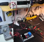
Q1 heatsink is at 39C after 3 hours of 445V input and 375V output. Total current through Q1 is 50mA, with 30mA to 12.4K load.
I have cycled it numerous times on-off and it seems to be ok with that. The Q1 FET is rated for 60W (800ma). It's also 4.5 ohms Rds so that helps a bit too.
I'm using 2 of these in my Class A amplifier. This one will supply the driver, long-tail pair and differential CCS. The other will be for the screen supply, where I'll be at 350V out but total current at 75mA. For that regulator, I will probably heatsink Q1 as I've done with Q3 (see picture) as it will have more differential and current.
I am looking forward to hearing the difference between this and my present "Maida" regulators. If it's anything like my DAC, it should be fantastic.
Attachments
Looks like running great then. Congrats. Will need that silver sink, at 375V 20mA spare is 7.5W constant. You may try a bit more if the thermals will allow, if it can give you some more sonic. You will judge after you get familiar and the build is a bit run in.
373.7 on the FLUKE 45 is the drift from 375 after 3 hours? 445 on the FLUKE 75 is from a bench PSU? Is it tube or SS?
373.7 on the FLUKE 45 is the drift from 375 after 3 hours? 445 on the FLUKE 75 is from a bench PSU? Is it tube or SS?
Looks like running great then. Congrats. Will need that silver sink, at 375V 20mA spare is 7.5W constant. You may try a bit more if the thermals will allow, if it can give you some more sonic. You will judge after you get familiar and the build is a bit run in.
373.7 on the FLUKE 45 is the drift from 375 after 3 hours? 445 on the FLUKE 75 is from a bench PSU? Is it tube or SS?
I think that sink is only 2C/W heat rise, pretty minimal. However, I have a plan that will set both regulators on to the same aluminum heatsink, with both Q1 and Q3 tabbed directly to the sink below, as the photo shows with Q3. I agree with you, the better the thermals, allows for better sound when it comes to regulators, and as a bonus, they last longer.
Yes - after 3 hours. It was set to exactly 374, so it's out by 300mV. Salas should be happy with that.
The beige box is a bench supply I built with a spare Hammond transformer. Added the 193N choke after to get noise right down, but no room inside. It also has a 3A, 6.3 (linear) filament supply. The filament supply is floating at 1/4 B+ for circuits that might need this.
Tube or SS:
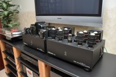
My amplifiers are tube, 6L6GC running 4 tubes push-pull parallel per side. The power supply chassis is separate. They produce 42W RMS per channel from 20Hz to 30KHz +/-0.3dB, with 0.25% distortion. The output transformers are from a Sansui AU-111 tube amplifier, so I am taking advantage of the 10% cathode feedback tap in the output circuit. They sound very good now, but I'm confident your great regulator design will send them over the top. I have 2 (two) pairs of these, picture attached is just one pair. The logo and name are mine, but these are one-off amplifiers built for me. You cannot find those output transformers anywhere so making more is out of the question!!
Attachments
It's possible you can still get them, mine are original. That's Isao Asakura's website, nice man, we swapped lots of emails when I started my design.
I posted my amp details in context of Salas' shunt regulator being used there, so we shouldn't post any more on this subject in this thread.
Regards,
Gary
Yes - after 3 hours. It was set to exactly 374, so it's out by 300mV. Salas should be happy with that.
That's impressive drift indeed for that scale of voltage in a hot reg when coming from an innocent for noise and complexity JFET and resistor non feedback Ref. What is it 0.08%? And we can trust the FLUKE 45 stability I guess.
Nice amps by the way.
That's impressive drift indeed for that scale of voltage in a hot reg when coming from an innocent for noise and complexity JFET and resistor non feedback Ref. What is it 0.08%? And we can trust the FLUKE 45 stability I guess.
If you're happy...I'm there too.
Thanks! (they were only 18 months in the planning and building of the 2 sets)Nice amps by the way.
As I mentioned, my only concern - if it's one at all, is the very dynamic nature and magnitude of the screen current. With the low z out of the SSHV2, it should handle this well.
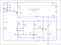
There is SSHV1 negative.
Hi Salas,
A general question (to all).
When there is a separate power transformer winding for negative supply (either low or high voltage), is there any possible drawback in using a positive regulator for that negative supply?
Power amps are weird in how they receive regulation. You will test in practice soon.
I've been using the Maida (LT1085) regulator with an IRF840 for a pass element for both screen and driver. When I was doing the build originally, you had not yet done the SSHV2. I went with the Maida because it was stable and I had done lots of bench testing. That's all changed now. The large filter caps I required for the linear regulators (100uF) on the amplifier will become unconnected monoliths.
Just waiting for teabag to finalize his group buy and once I have another board, I will begin testing on the amp.
Thanks!
Hi Salas,
A general question (to all).
When there is a separate power transformer winding for negative supply (either low or high voltage), is there any possible drawback in using a positive regulator for that negative supply?
To the contrary, using two positives with two bridges arrangement, gives you two identical same genre semiconductor circuits and ground loop safety.
There is SSHV1 negative.
Hi Salas,
thanks for your quick replay.
Where can I find it?
Anto
To the contrary, using two positives with two bridges arrangement, gives you two identical same genre semiconductor circuits and ground loop safety.
Thanks.
Hi Salas,
thanks for your quick replay.
Where can I find it?
Anto
It was a few pages behind I mentioned it again, but here again not to be searching.
Attachments
- Home
- Amplifiers
- Power Supplies
- Simplistic MosFET HV Shunt Regs