This powers a pair ECC81, on a buffer stage, eating 225v./60mA.
I placed a dummy load resistor: 13k7/8w.
And expect to fix 800mV. on TP but never got start the module.
With your high drop near 100V and 80mA the CCS will have to dissipate 8W! Is your PCB sink capable? Lower drop drastically with capable CRC or RC alone. Your dummy will need to be 3K7 20W. Its stressed everywhere I am afraid as you did till now. Also check insulation of Mosfets. Its possible that you hit its input hard with 2X320VAC Tx before it conducts any current for the CRC to drop some.
P.S. ECC81 eating 60mA??? Is there solid state also there?
I try to upload the picture again:
An externally hosted image should be here but it was not working when we last tested it.
I place the original 47k resistor between caps, but surprise only one volt drop.
From 325 to 324v to be exact.
I don't know how to further down voltage here.
And concerning the 60mA consumtion, I remember to measure something as 0.06A with my cheap multimeter. But again not very confident with anything, I am a beguinner here.
Tubes are a pair of good sounding Brimar 6060 "T"yellow logo, I think these are audiophiles ECC81. Nothing more.
I think now succed:
OK. Its a typical CRC. Take out C13 C14 and C20. That is we will try RC input to tame down the high 320VAC transformer. Its capable of 425VDC on C input even with losses. Sure that your buffer needs 60mA and not 6mA? Two ECC81 sounds like 6mA to me if there is nothing extra eating power.
If 6mA, use R1 2.7K 10W, set reg for 0.3V on TP, 37K 5W dummy.
If 60mA load, use R1 1K 20W, set reg for 0.8V on TP, 3K7 20W dummy.
Use 1uF plastic 400V directly across reg input if you got long cable from rectification or some other small value.
I place the original 47k resistor between caps, but surprise only one volt drop.
From 325 to 324v to be exact.
I don't know how to further down voltage here.
And concerning the 60mA consumtion, I remember to measure something as 0.06A with my cheap multimeter. But again not very confident with anything, I am a beguinner here.
Tubes are a pair of good sounding Brimar 6060 "T"yellow logo, I think these are audiophiles ECC81. Nothing more.
Its you got no consumption yet, thus no drop. Please measure that 0.06A again or better show here the buffer schematic.
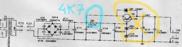
Also is your Tx really 320VAC if you measure AC on its output? (be careful). If you talk DC after bridge by mistake then we have to keep C13 and use only 10W 2K7 or 1K R1.There is 320v on secondaries,
I am not very confident to be able powering on the unit again as stock. I failed once and do not wants to repair. So sorry, no further reading the consumtion.
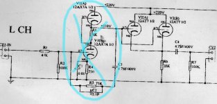
Attached is schemantic, the tube section on Jolida tube tuner 402.
Blue marker shows deleted components as no need for gain stage. Active components are only two tubes 12AT7.
Then the power transformer, I unplug the secondary winding and read AC 230v.
One queston more please, I have as spare three good PIO capacitors ASC brand, also called "oil can" values 10, 10 and 30uF. I think these ae wonderful for tube power supplies, may I substitute the litlle lytics 100uF that come in stock?
Also I have spare double C choke 10H/160mA. Do is SSHV2 benefit from these further smoothing?
If you delete that section then there is no reference and blocking for the next section. Also that last parallel 12AT7 section can not normally draw 60mA when rightly put together. That would be KT88 class A territory. Its wrong what you do I am afraid. SSHV2 alone you can test on dummy load with the 6mA standard and the associated guide for ~320VDC CRC and load I had given above. It will like PIO and choke also. But you should keep R1 for proper drop whatever the final pre-filter. Since I see many aspects not well defined in what you try to put together, I suggest you seek local help from some tube expert fellow so to convert and test for a correct standalone buffer and to set the reg safely for it. HV needs caution. Also watch the insulation and input safety of cheap DMM when measuring HV especially in series. I don't recommend you proceed alone, there are many weak points in the plan already and the reg reacting with smoke is a bad sign.
This circuit is a cathode follower, in parallel, also known as "buffer". It's a capacitor input not seen on schematic, also 47k gird choke on input and ouput. I do not specify this minor changes as I show the schematic for consumtion puposes. Although is good sounding you are right, I always can do better, and now will check other single stage ciucuits no need for paral.lel. Lucky to find now an standard cathode follower ECC81, (proof engineered) HV 250v, and consumption 4,55mA per channel, so 9-10mA the whole tube (stereo).
Dummy load should be 250/0,01= 25k, 8 or 10watts.
Dummy load should be 250/0,01= 25k, 8 or 10watts.

SSHV2
Salas,
I have my Version 2 up running and everything looks good. I've been trying to tune the current to about 10mA - 100mv as of the instruction, but stopped at 176mV and couldn't go any lower. I can trim the voltage to 140v as desired. The input voltage is 172v. Boards and parts are from Teabag. Any clue ??
Albert
BTW the dummy load is 15K 10w
Last edited:
There are two breaks. One for max current which is near DN2540 sample IDSS (Q2 IDSS as close as R5 is allowing), one for minimum, as near to Q2 off as (maxR4//R3)+R5 allow. You may notice a 20-100mA operational region printed on the instructions schematic (about). When you want 10mA for your load, trim for +20mA spare. I.e. 30mA in total or 300mV T.P. reading. That extra 20mA caters for the internal consumption needs of the reg and it ''massages'' the shunt Mosfet enough to keep the output impedance spec respectable. Your test dummy is OK for simulating ~10mA @ 140V load consumption. Some of the rest is gonna burn for internal biasing but mainly on Q3's sink. The spare current thing is also mentioned in the instructions text.
Salas,
What a good design you have. It's so stable that I don't have to adjust the voltage after 3 hours listening.
I now only have one reg for 2 channels and set the current at 23mA. The bass line is better than the version 1 for a good margin. With version 1, I found the bass thin with my LL1660SE 10mA, the weight of bass is more and solid with the version 2, and more details too.
A little off topic, the wave-form with the 1660 doesn't look too good and sounds compress too. It looks very ugly after 4.5k even with 0.1 & 4.7k across the output. I'd like to try without the opt and see how it sounds like. Can I run the reg direct to the 26 anode from it's output point, or I have to series a load in between ??
Thanks
Albert
Attachments
- Home
- Amplifiers
- Power Supplies
- Simplistic MosFET HV Shunt Regs