Sounds wonderful. There is a GB on SSLV etc going on. No chance that SSHV2 will be availiable on the same GB?
best regards
Staffan
Later, we still evaluate.
Yes, 5mV on my 20Mhz scope.
Also the time/div fully clockwise I see. Good.
Yes, 5mV on my 20Mhz scope.
Phelipe, you tested on a dummy or in circuit?
Old tx with dummy, Bartolucci tx with circuit but mosfets HV reg protected with zeners
")
Salas,
is there a way to have the first post able to be updated with an index?
That index could shows which posts have data (pics/schematic/equations/etc) that need to be consulted by all/some builders.
It would precede the original first post. The only person in addition to the Moderators that can update that index post would be the originator and the normal 30minute restriction would be permanently removed.
Is this worth considering for the new Forum software that is being readied to roll out?
Salas, I cannot find the post number for the SSHV2. The search egnine brought me there at first, but now is taking me to a later iteration by one of the testers and it doesnt have the schematic.
http://www.diyaudio.com/forums/power-supplies/134801-simplistic-mosfet-hv-shunt-regs-207.html
Salas,
is there a way to have the first post able to be updated with an index?
That index could shows which posts have data (pics/schematic/equations/etc) that need to be consulted by all/some builders.
It would precede the original first post. The only person in addition to the Moderators that can update that index post would be the originator and the normal 30minute restriction would be permanently removed.
Is this worth considering for the new Forum software that is being readied to roll out?
Don't know if possible, this is Jason to ask who configures the software.
But the mods can add something link if requested I suppose for now.
SSHV2 schematic and explanation! pg.207
Here is SSHV2. Same parts count as SSHV, same concept. I put it first in the picture in mid summer. My goals were: 1. More resolution but unchanged musical tone from previous version. 2. Better voltage stability. 3. Adjustable constant current setting on the fly.
I was content at a point, but I wanted to know if users of the popular previous SSHV will find it truly easy and better. So I kindly asked two members to give it a go on their own construction approach, no specific build guide. That was to check if its technique & layout tolerant and how they would like it on different applications. Incidentally both live in Mediterranean islands. First guy runs it for over a month now, had made various builds. Second guy is about to finish his first. They will give you their feedback eventually I believe.
As you can see its cascoded both for CCS and error amp. That is to increase CCS performance and error amp's current/thermal stability. The Q1,Q2 Supertex DN2540 DMOS CCS runs only Q2's Vgs across R4 trimmer that can take the low dissipation, also aided by R3. Because each DMOS has own IDSS just like a JFET, the trimmer not only homes in to the current we need to set, but saves calculations, and of course can be changed at will when the circuit is live. R5 is a safe break and test point. Setting 40mA CCS should read 0.4V across R5 T.P. for instance. R1,R2 gate stoppers should be closest to gates, D1, D2 are Zener protections.
The error amp Q4,Q5 is based around superior PNP Sanyo FBET types (cheaply available as Fairchild) and runs 3 times the current of previous SSHV. Due to voltage sharing across the cascode, current is better SOA tolerated and drives Q3 Enhancement mode MOSFET's input capacitance stronger in high frequency. For easy sourcing reasons, MJE350 has been tested compatible too. Up to 300V that was, without mini sinks on Q4, Q5. Mini sinks are recommended for higher Vout or when in hot enough surroundings. Good for long term reliability anyway.
The Vref is based on Q6 Toshiba 2SK117GR low noise, that showed better drift than previous due to different output conductance and D4 LED's counter thermal coefficient action to Q5's Vbe. R11 trimmer sets Vout, and is R12 ''bypassed'''. C2 noise filtering has been increased to big enough practical MKP size, D3 protects the Vref along initial slower charging time than before. Zobel termination has been adjusted to the now total ''faster'' reg. C1 is MKP too. Both capacitors quality is thought subjectively influential.
Due to the cascode CCS better HF PSRR a 47uF MKP capacitor can be enough for the raw DC, especially if CLC filtered, so to have a chemical capacitors free PSU.
Due to the speedier circuit, 4 wire remote sensing output has been judged useful to be incorporated. It got tested with such output only, without problems. In tube builds that things tend to be lengthier for wiring due to heat and size of active components, R.S. can make a perceivable difference. The 4 wires can be shorted right at the reg's output of course if it has to drop in an existing two wire run. I.e. S+ & F+ be turned to one +Vout node, as S0 & F0 to one ground node also.
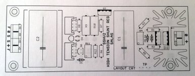
To be thorough I had even consulted a double layer PCB layout with Crt. You can follow it as a general orientation example to put together your own build. Perforated board works fine also and the circuit is same parts count as before.
SSHV2 is conservatively rated as 400V input & 380V output. 20V drop over it is more than enough to regulate well, hence the smaller on board CCS sink. Calculate/test that your transformer and rectification provides at least 10V raw DC more than your Vout goal when your mains are at their worse low. Most of dissipation happens on output MOSFET and is Vout*(CCScurrent-Loadcurrent) in Watt, exactly as you know from previous versions. That will take a main external side/parallel sink of course. If your raw DC in is large for some existing trafo reason check the drop over Q1 ~(Vin-Vout) times the CCS current, maybe you want to add Q1 on main sink too. Well, that's all folks.
Attachments
Last edited:
Dang. Was searching all over the place for something to use for R6 in the Merlins BOM on #2082 . It says 1R86 but a quick look at the schema says 1R8 right?
What kind of resistors are you using btw? Metalfilm 1% often has a voltage rating at 200 V, carbon film like 250.
Staffan
What kind of resistors are you using btw? Metalfilm 1% often has a voltage rating at 200 V, carbon film like 250.
Staffan
Last edited:
Dang. Was searching all over the place for something to use for R6 in the Merlins BOM on #2082 . It says 1R86 but a quick look at the schema says 1R8 right?
What kind of resistors are you using btw? Metalfilm 1% often has a voltage rating at 200 V, carbon film like 250.
Staffan
1.8 or 1.86, that's 3% difference. Don't think the precision of that resistor is critical here,..... I guess higher value will provide more damping (by a hair) ... while I guess a lower value will lower Zo (by an even thinner hair) at the expense of increased risk of oscillation....
I'd guess 1.5 to 3 Ohm would do here, and you can play with the C.
SSHV1 was using 3R3 / 1uF in that position...
With such a low value, you will not hear any difference between resistor types as far as noise is concerned
Last edited:
Just look at the schematic if there is some difference around, when the time comes I will write a small PDF with quick guide and any final changes if they will occur. Yes, its 1.8 Ohm 0.25W. I use metal film there. Should be easy to get data over the web for known resistors, the test boards typically used Philips (BC/Vishay) with no problems.And there are HV cheap ones also, for instance. Keep in mind that only R9 & R10 carry the full Vout and that is split by two across each. The others work nested in low voltages, and R6 sees almost no current, thus almost no drop.
I'd guess 1.5 to 3 Ohm would do here, and you can play with the C.
SSHV1 was using 3R3 / 1uF in that position...
With such a low value, you will not hear any difference between resistor types as far as noise is concerned
They are different regs in frequency and damping characteristics, avoid SSHV1 values, playing especially with C1, R6 Zobel in SSHV2 is not recommended.
They are different regs in frequency and damping characteristics, avoid SSHV1 values, playing especially with C1, R6 Zobel in SSHV2 is not recommended.
Can't you just keep the same cutoff frequency by adjusting C ?
(for ex, if you only have 2.7 ohms , you use 220nF ?)Of course this will change Q by a factor 2, but is it critical to the stability?
- Home
- Amplifiers
- Power Supplies
- Simplistic MosFET HV Shunt Regs