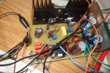
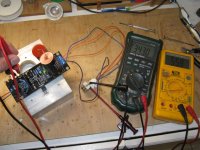
Here is my SSHV2. Row pcu, heater psu and SSHV2 all in one pcb 10x15 cm, including the sinks.
I made some changes in layout of SSHV2, to use the same sink for IRF840 and DN2540. I replaced 2sk117GR and KSA1381 whith 2SK170 and mje350, and I used 10u/450V electrolytic. I used 4 uf4007 rectifiers and 4 // 47n/680V, and after that RC filter (2 100u/400V electr., 2 1u /400V MKT, 1 10u/400V electr. and 2 resistors)
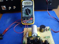
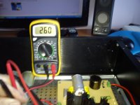
The in + raw is 298V. After power on I turned R4 and R11 for 30mA and 240V, then I conected my preamplifier and power on again.
The reading started from 235V, then rised slowly to 245V (in about 15 minutes) and then stay steady as rock for about 2 hours I lisened to music. I tried that next day and once again for more than 2 hours. The readig was the same as the first time. The sink was just warm. I hear no hum, buzz and other noise at all.
The sound was very clear and detailed for for bass, mind and high.
I love SSHV2. You can use it as variable psu
The only I have to say is congratulation Salas
I tried to attach two pictures but Iwas waiting for more than 1 hour and nothing. Perhaps tomorow I' be more lucky
I made some changes in layout of SSHV2, to use the same sink for IRF840 and DN2540. I replaced 2sk117GR and KSA1381 whith 2SK170 and mje350, and I used 10u/450V electrolytic. I used 4 uf4007 rectifiers and 4 // 47n/680V, and after that RC filter (2 100u/400V electr., 2 1u /400V MKT, 1 10u/400V electr. and 2 resistors)
The in + raw is 298V. After power on I turned R4 and R11 for 30mA and 240V, then I conected my preamplifier and power on again.
The reading started from 235V, then rised slowly to 245V (in about 15 minutes) and then stay steady as rock for about 2 hours I lisened to music. I tried that next day and once again for more than 2 hours. The readig was the same as the first time. The sink was just warm. I hear no hum, buzz and other noise at all.
The sound was very clear and detailed for for bass, mind and high.
I love SSHV2. You can use it as variable psu
The only I have to say is congratulation Salas
I tried to attach two pictures but Iwas waiting for more than 1 hour and nothing. Perhaps tomorow I' be more lucky
Last edited:
Allthough I'm not so good in listening, I think I hear more detail in music. I used a TL783 as +B that works like a LM317 and simple RC filtering. My pream. is a tube pr. whith 2 6n3, but I'll test whith an other tube 6n1. http://diyaudioprojects.com/Tubes/ECC802S-ECC82-12AU7-Tube-SRPP-Preamp/
Last edited:
With lower Vref resistors. Make them half.
Hi Salas,
You mean R11 and R12?
Thanks
Allthough I'm not so good in listening, I think I hear more detail in music. I used a TL783 as +B that works like a LM317 and simple RC filtering. My pream. is a tube pr. whith 2 6n3, but I'll test whith an other tube 6n1. DIY ECC802S (12AU7 / ECC82) Vacuum Tube SRPP Preamplifier
TL783 is 125V max. You floated it I suppose for the B+ of that SRPP.
Very nice. I will try it out more later and I can include V3 calc with the SSHV1 evolution post linked from page 1 for everybody to can point to and have less questions. With your permission of course. Is that OK?
Of course that's OK!

P.S. With the last included schematic ''current reference'' cells should read ''LEDS Voltage'' D1,D2,D3 to match I think. You also include a rectification & pre-filtering drops calculation section. Would be better to depict that front end example with a schematic too, so people will picture it better?
Yes, I'll try to do it tonight after work. Maybe you should wait till then before putting the link in the first page...? I'll post here once it's done.
125V is the limit between Vin and Vout. B+ was 220V and floated.TL783 is 125V max. You floated it I suppose for the B+ of that SRPP.

SSHV2 beta test
Another very successful best test for the SSHV2.
A few days ago, I received from Teabag one SSHV2 pcb to test. Quality is awesome as usual.
This morning got the last few parts missing and soldered it. Took less than two hours. Worked right away, no surprises. Current initially was on the low side, and it did not regulate properly. A few turns on the trimmer and everything was fine. Looks very stable, with minimal voltage drift. Of course, this can change inside a box.
Looks more bulletproof and more tolerant to mistakes than SSHV1.
Tried various Vin and Vout combinations on the high voltage side.
Current set a 55mA, but I have tested it up to 100mA.
Also heatsink for the 840 was a little oversized for testing. For the 10uF cap, I had to use two 20uF 250V in series, as I did not have anything else in my stash right now. Resistor was 17k.
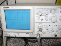
Pic on the scope is AC full gain.
Many thanks to Salas and Teabag.
Another very successful best test for the SSHV2.
A few days ago, I received from Teabag one SSHV2 pcb to test. Quality is awesome as usual.
This morning got the last few parts missing and soldered it. Took less than two hours. Worked right away, no surprises. Current initially was on the low side, and it did not regulate properly. A few turns on the trimmer and everything was fine. Looks very stable, with minimal voltage drift. Of course, this can change inside a box.
Looks more bulletproof and more tolerant to mistakes than SSHV1.
Tried various Vin and Vout combinations on the high voltage side.
Current set a 55mA, but I have tested it up to 100mA.
Also heatsink for the 840 was a little oversized for testing. For the 10uF cap, I had to use two 20uF 250V in series, as I did not have anything else in my stash right now. Resistor was 17k.
Pic on the scope is AC full gain.
Many thanks to Salas and Teabag.
Attachments
Another very successful best test for the SSHV2.
A few days ago, I received from Teabag one SSHV2 pcb to test. Quality is awesome as usual.
This morning got the last few parts missing and soldered it. Took less than two hours. Worked right away, no surprises. Current initially was on the low side, and it did not regulate properly. A few turns on the trimmer and everything was fine. Looks very stable, with minimal voltage drift. Of course, this can change inside a box.
Looks more bulletproof and more tolerant to mistakes than SSHV1.
Tried various Vin and Vout combinations on the high voltage side.
Current set a 55mA, but I have tested it up to 100mA.
Also heatsink for the 840 was a little oversized for testing. For the 10uF cap, I had to use two 20uF 250V in series, as I did not have anything else in my stash right now. Resistor was 17k.
Pic on the scope is AC full gain.
Many thanks to Salas and Teabag.
That's a very good new, thanks George, Nick & Mike for your excellent work
")

That's a very good new, thanks George, Nick & Mike for your excellent work
Black proto group test board for the burns not to show much.
- Home
- Amplifiers
- Power Supplies
- Simplistic MosFET HV Shunt Regs