Have you taken out and measure ALL the semiconductors and make sure they are OK? Do that before next try.
I changed all semis
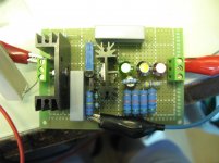
Solder the Vin cables directly under Vin capacitor electrolytic.
I have to change all LEDs, once changed & Vin cables soldered directly to 150uF input cap, can I fire up?
Then if everything is fresh, fets insulated from sink, there must be a short somewhere in the board. Clean and check. Maybe check continuity of output to ground. It shouldn' t be short.
No continuity at the output. Thanks for help George
")
The orientation of all SS devices should be double and triple checked. Also the value and Ohmic resistance of all resistors should be double and triple checked. Once both the above are correct and there are no short circuits on the PCB, the regulator should work fine. "Haste makes waste".
I have to change all LEDs, once changed & Vin cables soldered directly to 150uF input cap, can I fire up?
Done, I have to do something more or can I fire up?
Yes, best to take a break. Check everything with a fresh mind some other time. Check the pcb carefully for possible trace shorts via solder. Take all parts out and start anew. Also make sure you give it filtered DC from a trusted source. I suggest you use some zener diodes to protect the mosfets.
Dear Salas
After burnt 4 FETs, 2 resistors and 3 LEDs, finally there is output at the SSHV1, with 300V input, I connect a 5.6K resistor at the output as load then adjust the VR to have 260V output. The output voltage slowly drift up to 300V and the IRF840 become very hot. Please help!!
After burnt 4 FETs, 2 resistors and 3 LEDs, finally there is output at the SSHV1, with 300V input, I connect a 5.6K resistor at the output as load then adjust the VR to have 260V output. The output voltage slowly drift up to 300V and the IRF840 become very hot. Please help!!
Attachments
I am glad to be in good company. Fried all my fets, LED's, R1, and the gate stoppers by plugging an unloaded power supply cable. 485V not good on 400V parts. Lost alot of magic smoke on that stupid mistake.
Point taken "Haste makes Waste"
Having a bench HV power supply really helps here in trouble shooting. A Variac is also good if you have enough meters to monitor voltage and curent draw.
Point taken "Haste makes Waste"
Having a bench HV power supply really helps here in trouble shooting. A Variac is also good if you have enough meters to monitor voltage and curent draw.
Dear Salas
After burnt 4 FETs, 2 resistors and 3 LEDs, finally there is output at the SSHV1, with 300V input, I connect a 5.6K resistor at the output as load then adjust the VR to have 260V output. The output voltage slowly drift up to 300V and the IRF840 become very hot. Please help!!
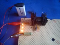
For what reason it burned components and now gives output? Were they connected differently than now, or it was random burn outs? You either need a bigger sink (did not tell the current you use, the sinks look small), or 840 is in oscillation. Use the oscope. Put a little sink on the Jfet.
I am glad to be in good company. Fried all my fets, LED's, R1, and the gate stoppers by plugging an unloaded power supply cable. 485V not good on 400V parts. Lost alot of magic smoke on that stupid mistake.
Point taken "Haste makes Waste"
Having a bench HV power supply really helps here in trouble shooting. A Variac is also good if you have enough meters to monitor voltage and curent draw.
Talking about the one you had working on your 6V6 CF?
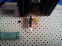
This morning I make a P2P only for CCS, 220R gate resistor IRF9610 burned, IRF9610 also burned, LEDs still alive verified with 9V battery, also verified that metal tab of IRF9610 don't have continuity with heatsink and IRF9610 was new.
Attachments
Last edited:
For what reason it burned components and now gives output? Were they connected differently than now, or it was random burn outs? You either need a bigger sink (did not tell the current you use, the sinks look small), or 840 is in oscillation. Use the oscope. Put a little sink on the Jfet.
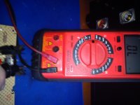
Previously no output because I revise the 2SK147 and burnt one resistor. All others dead were due to accidentially short the Q1. I reconnect all the wire and measure the voltage again. This time I connect a 8.6K resistor as load and the max. output is 270V with 300V input. Any smaller resistor will cause the output voltage dropped. Seems the output current is limited at 30mA. I think the measurement in my last message was wrong because the load resistor may not be connected properly.
This morning I make a P2P only for CCS, 220R gate resistor IRF9610 burned, IRF9610 also burned, LEDs still alive verified with 9V battery, also verified that metal tab of IRF9610 don't have continuity with heatsink and IRF9610 was new.
Are those 9610s IR made? Where bought from? Having any other PMOS like 9240 to try?
Previously no output because I revise the 2SK147 and burnt one resistor. All others dead were due to accidentially short the Q1. I reconnect all the wire and measure the voltage again. This time I connect a 8.6K resistor as load and the max. output is 270V with 300V input. Any smaller resistor will cause the output voltage dropped. Seems the output current is limited at 30mA. I think the measurement in my last message was wrong because the load resistor may not be connected properly.
Your burn story has logical explanation then. What R1 value you use and what will be your real load current need?
- Home
- Amplifiers
- Power Supplies
- Simplistic MosFET HV Shunt Regs