Using the board is the reg thing. Serves a purpose, given you need a reg. Recommended parts for the reg itself ensure it will perform as intended. If to compromise for economical reasons, do that for C2 only. C1 is more sensitive for ESR as it is a part of a tuned Zobel. Use MKT C1 at least. There are also MKT for C2 maybe economical enough. I suggest you go try a prototype with the economics you can allow, and see if you get it to work properly first. Its regulating ability will show first and you will judge what it brings to your application. If all will go well for you, you may try putting better capacitors on it later.
Is there anyway to up the time constant to allow C2 to be decreased. Even decreased to 4.7uf is exponetially more economical and diverse in selection of a film cap that 10uf. At 10uf about the only choice that make sense is a motor-run oil cap. Going below 4.7uf and there are a huge number of choices.
Is there anyway to up the time constant to allow C2 to be decreased. Even decreased to 4.7uf is exponetially more economical and diverse in selection of a film cap that 10uf. At 10uf about the only choice that make sense is a motor-run oil cap. Going below 4.7uf and there are a huge number of choices.
Depends on how much PSU noise you can allow in your application. A phono stage is not a low gain line stage, etc. I found 10uF a good spot. Why not parallel 2 4u7 or 3 3u3? For single cap, SCR/Solen has a good compact MKP at 10uF, there are Wima radial, there are also some MKT for cheaper, or even Ebay MKP ''Audiophiler'' thingies at 10uF 400V.
Power Supply Testing, Model and Physical
Hi Salas,
What would be the correct way to load and test the supply? Is a linear resistor really representative of the slightly more complex dynamic load of the tube (Or whatever load) being driven
If LT Spice was used, what would be done there to check the supply output impedance vs frequency?
Thanks!
Gary
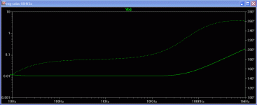
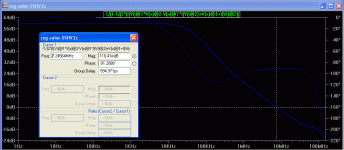
After its set with sources, you assign 1 as AC amplitude to the voltage sine source and also to I source load, you turn on the parametric probe and and you probe ''out'' point in logarithmic by clicking to the chart's left and choosing. Or in linear and Ohm if you assign out/1A function. For OLG I use the Tian method of internal loop breaking. There is an LTSPICE thread in diyA, there you can ask more.
Attachments
After its set with sources, you assign 1 as AC amplitude to the voltage sine source and also to I source load, you turn on the parametric probe and and you probe ''out'' point in logarithmic by clicking to the chart's left and choosing. Or in linear and Ohm if you assign out/1A function. For OLG I use the Tian method of internal loop breaking. There is an LTSPICE thread in diyA, there you can ask more.
Thank you!
Okay, so instead of a resistive load you use a current source. Which is really a "sink" depending on which way it's oriented...?
I'll check out the LTSPice thread.
What is OLG?
Gary
Hi Salas,
What about getting 390 volts from SSHV2? I would like to regulate the driver stage (Allen Wright's differential cascode driver with 6N6P "Ruskies") of a PP amp I'm about to build. My B+ would be in the range of 450 volts, but I could drop it with an RC filter to 410 volts for feeding the regulator input. Do you think that would be feasible?
Thanks.
P.S. Don't you ever sleep? Sending a post at 4:51 AM?
- Home
- Amplifiers
- Power Supplies
- Simplistic MosFET HV Shunt Regs

