Salas uses 2N6520, Quanghao uses MJE350 for all Vout changing some resistors values on his pcb, so if you intended to use Salas schematic I will put 2N6520 & if you will use Quanghao pcb you can use MJE350.
MJE350
VCBO 300V
VCEO 300V
2N6520
VCBO 350V
VCEO 350V
So I should go with higher voltage version then. I cant buy 2N6520 in my country, but they do have BF493S (also 350V), so I hope it will work well as substitute.
My schematic has MJE350 for up to 300V. QH has shown some 340V Vo build with the same transistor still holding. That is certainly beyond its datasheet max, thus I can't recommend it for reliability. You may try it for a bit over 300V but its your responsibility. Some newer production wafers for those are more rugged than when the specs were made it seems, they are old designs. Those TO-92 you mentioned can be certainly used since they make the spec. Use mini sinks on TO-92. I would still prefer the larger format MJE5731A 400V that member Hearinspace have used successfully if you can find it. The reg has proven elastic for hosting different driver transistors up to now, but the main thing is those transistors to prove stable themselves when near their max.
finished the positive part of my dual 300V supply for Exstata. Its P2p.
The heatsinks are a bit small (the ones for exstata's PSU), so the tempereture on the heatsinks stabilized after 15 minutes.
For irf9610 to 50 C, and for irf840 to 80C
(A bit high i guess. Adding bigger heatsinks is a problem in my chassis design, so i will add a fan. For test i just put up a 12'' PC-fan, and the tempereture fell to only 40 C
I also measured the V-out during warmup, and there was quite a nice linear correlation between V-out and tempereture of (the heatsink of) irf840. V-out raised roughly 0,5V per degree C. Is that normal??
The Jfet current is susceptible to its thermal environment. There is enough drift until settling always, due to direct translation in voltage on the large value reference resistor. The more heat or suddenly blowing air in there the larger the drift or change. I still prefer the low noise easily filtered with small MKP & subjective results with that simple passive voltage reference than using a high voltage Zener that would be very tight in wandering. Drift is a nuisance, needing to watch it and trim for ballpark settling value in final installation. I have mentioned there will be such a thing from the very first posts. So in this reg concept it is normal to answer your question. Accentuated in your build non the less.
Ok, MJE350 will propably survive 300V Vout, will try. I will have 350V in and 300V out. Should I also change resistors R3 to 82k and R4 to 220k when Vin is 350V?
Thanks.
MJE350 has 300V Vceo spec no doubt. Not so high Vo to make other changes pressing, just use R3 68K 5W for more comfortable dissipation I would think.
Hi Salas,
on more question from me.
Is it OK to use the 2N6520 even for voltages lower than 200V, or it is recommended to use the MJE350?
Both work as it proved. 2N6520 is lower Cob and higher Ft. Below 200V it will dissipate comfortably too. You can try MJE also and decide on subjective grounds.
That´s the problem. Nobody has them in stock. I try to get a quote from Caddock directly.
I wouldn't use any high wattage resistor in the audio aplication , which has only 1000h
 liftime , no mettter how others good parameters it has
 read the data more carefully
I wouldn't use any high wattage resistor in the audio aplication , which has only 1000h
read the data more carefully
Load life changing value not life time.
Load life changing value not life time.
merlin , it's the question how you read the data
As I see it , the producer confirm during the 1000h of work , there will be no failure and max resistance change will be less then 0,5%
after those 1000 h producer can't guaranty anything
just for the compariton
MBE0414 Beyschlag 50ppm - 33 cents/ pice
after 1000h - delta R less 0,4%
after 8000 h - delta R less 0,8%
Those Caddocks are designed for aerospace , where there is a strict procedure what kind of elements you have to change after exact working time ( they calculate it )
I doubt you have some notice how many hours you use your audio system every day
Beyschlag ? no thanks
it's power supply not signal path
when you open medical equipment ( where psu is really important ) you will see a lot of MBE0414 from Beyschlag there
But if you can afford to spend 60$
: or more  for one resistor you can allways order Vishay S106Z - with desired value
you will get 2ppm, noninductive design and long term stability
If possible count in me for 3 or 4 resistors?
I will ask a quote for Vishays, do you want to know the price?
No, thanks. I hope i have luck and a friend has one or two of the Caddock´s
No, thanks. I hope i have luck and a friend has one or two of the Caddock´s
You are fortunate to have a friend with Caddock's, if your friend have 1 or 2 for me I will appreciate very much.
Question - PS turn on surge and the IRFP9240 maximum Vds
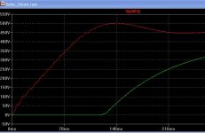
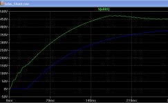
I have a power supply that when steady-state, is about 465V. however, at turn on, it's just around 500V. It runs the plate supply, I also need to run the Salas shunt HV from this. I have modeled it in LT Spice. The Shunt output doesn't start ramping up until around 70ms, while on the source pin the supply is already at close to 500V. I'm using a CLC filter. Previously, I used a Maida Mosfet with no problems.
With a Vds of just 200V, I'm assuming that even for these few hundredths of a second the device would vaporize. Has anyone else had this issue, and what can be done?
Thank you for your help...
Attachments
Last edited:
I had shown a 150V 5W clamping Zener across it. But it must be short pin directly attached to it. Another solution is a 500V depletion mode CCS DN2540 Supertex. A bit drier sound, but less parts also.
Ok - thank you Salas, that worked out fine.
Is that what all of these parts are for??
The road to knowledge is a long, but fun one.
 :
:Attachments
What you show in the sim result? The addition of the clamping Zener? What parts you refer to, the enhancement mode CCS scheme parts?
Hi Salas -
I was just joking about the parts - inferring that I should have known a zener could have been used, but not obvious to me!
The simulation shows the addition of the 150V zener.
1 other question - the 1N5383 has a resistance of 330ohms. The 1N5378 (100V) has a resistance of 90 ohms. Would this be a better choice due to the lower resistance?
Gary
- Home
- Amplifiers
- Power Supplies
- Simplistic MosFET HV Shunt Regs