I have a couple LSK 389a ( 0-4ma I Believe) and was hoping I could sub it. Any problems?
Thanks Frank
Yes, it will work. Thanks for your first post.
Hi all,
Any more boards available?
Yup, I need a pair too
Cygnus & Piero, AFAIK nobody started a GB for Salas' HV Shunt (Simplistic or Simpler Simplistic) boards.
You must roll your ownOr P2P.
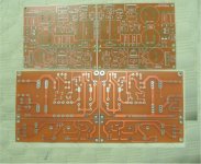
I can hepl you, if Salas allow me to use his design!
You can see my PCb test
Thank you
Attachments
I has open Group buy:
http://www.diyaudio.com/forums/grou...mpler-simplistic-design-salas-group-buys.html
http://www.diyaudio.com/forums/grou...mpler-simplistic-design-salas-group-buys.html
Thanks, sorry, but it's very hard to find info in 100 pages of posts, I tried.
D.
Is that: http://www.diyaudio.com/forums/atta...2-simplistic-mosfet-hv-shunt-regs-sshvopt.gif
http://www.diyaudio.com/forums/atta...49-simplistic-mosfet-hv-shunt-regs-ss300-.gif
So let's see if I got it right: I would like to build a regulator to drive 2 300B and 2 5842. In one word the tubelabSE.
Voltage is around 400 V, the tubes are biased at 75mA for the 300B and 17mA for the 5842. Total current 185 mA, let's make it 190mA.
I understood that I need to drop around 50V in the regulator, so I should have a DC rectified and filtered of around 450 V. Now first dumb question: this voltage is intended with or without load ? My transformer(400-360-0-360-400@280mA) has a DCR of 40ohm, and I added 100ohm before the tube rectifier (to be nice with him).
I have a choke 10H 81ohmDCR. Second dumb question: if I have a regulator do I need a choke ?
In the CLC filter I use now Solen Fastcap (22uF) and film cap (200uF). With the regulator, do I still need these expensive components ?
Should I put the good capacitor after the regulator ?
From my understanding I would answer that choke and fancy caps are not needed.
I understand I have to use a transistor with higher rating. Will the MJE850 work ? (specs attached)
From what I understood of the shunt regulators, they continuously dissipate in heat a portion of current. If the load requires more current, the regulator will send it to the load without decreasing the voltage.
So if I build for 400 V 0.3A max, the dissipation with no load should be 133 W. It means that I should have the possibility to dissipate this heat in the case the valves switch off (filament failure).
Sorry, but I am doing my best
Thanks,
Davide
Attachments
In such dissipations its tough luck. Member Disco had it on power amps and the heat was strong on pcb components, made the whole thing difficult to stay put. Imagine that it will have to run constantly above peak demand, not just bias. Heatsinking will be like running a big class A Mosfet amp. I would think of a series reg would be more practical.
As for the drop, it can do well enough with 20V difference also, so not to spare heat on CCS when set at strong currents. Those transistors you linked have a high Cob, the third one is for sustained 400V (5852). I would start with an MPSA-94, the dissipation on that BJT won't be much with 5k6 R5, the problem is the ambient temp if you try such a power amp thing. So that TO-220 you should have in stand by. Some CLC prefiltering proved smoothing out tone subjectively, blocks many kinds of gremlins it seems. But yes the PSRR of the CCS is much better than normal stuff. If you avoid it, especially in a power amp situation the choke would have to be substantial, you won't lose the earth. Forget hum anyway. But for power amp I still think its difficult to succeed practically. Anyway, if you try and having the heatsinks, good luck.
As for the drop, it can do well enough with 20V difference also, so not to spare heat on CCS when set at strong currents. Those transistors you linked have a high Cob, the third one is for sustained 400V (5852). I would start with an MPSA-94, the dissipation on that BJT won't be much with 5k6 R5, the problem is the ambient temp if you try such a power amp thing. So that TO-220 you should have in stand by. Some CLC prefiltering proved smoothing out tone subjectively, blocks many kinds of gremlins it seems. But yes the PSRR of the CCS is much better than normal stuff. If you avoid it, especially in a power amp situation the choke would have to be substantial, you won't lose the earth. Forget hum anyway. But for power amp I still think its difficult to succeed practically. Anyway, if you try and having the heatsinks, good luck.
Maybe it's a bit too ambitious with my limited knowledge of electronic. I end up with a water cooled power amp
I am surprise that in theory a regulator for HT should be a natural solution, but I could not find any almost-off-the-shelf solution. 99% of people continue to go with unregulated. I have built three amps, that share the same PSU, so I wanted to try what happen putting a regulator in the middle. One solution would be to use the regulator only for the driver stage, that require small current. In this way the stages should be decoupled. But most of the load variation is due to the output stage.
What do you think ?
Thanks,
Davide
I can hepl you, if Salas allow me to use his design!
You can see my PCb test
Thank you
quanghao, you have PM, if you decide to respond me... I need a pair of HV pcb
Maybe it's a bit too ambitious with my limited knowledge of electronic. I end up with a water cooled power amp
I am surprise that in theory a regulator for HT should be a natural solution, but I could not find any almost-off-the-shelf solution. 99% of people continue to go with unregulated. I have built three amps, that share the same PSU, so I wanted to try what happen putting a regulator in the middle. One solution would be to use the regulator only for the driver stage, that require small current. In this way the stages should be decoupled. But most of the load variation is due to the output stage.
What do you think ?
Thanks,
Davide
Ask Tubelab George what is the total idle and peak demand of his amp design so we can see the margins you got.
From my measurements, biasing the tubes with 75 mA each I had around 95 mA with 1 kHz signal at clipping. I should measure again, as I remember this number, but I was measuring something else.
The drivers have a CCS of 17 mA, so they should not drain more than 35 mA in total.
I think we should consider idle current 190mA, peak 250 mA.
I will ask George what number he has.
Maybe I should give a first try with the tubelab SE with 45. They need only 30 mA at 300V. So the requirements would be 100mA idle, 150 mA max @ 300V.
Thanks,
D.
You should set the shunt at +25mA above top consumption. With that current the shunt Mosfet will be working sufficiently on peaks.
This calculates to (250+25)-190=85mA @ 400V when the amp idles. That is 34W dissipation from IRF840 and about 7W from the CCS Mosfet if we assume 25V Vin-Vout at 275mA. I would never burn 34W on a TO-220. Are those numbers for two channels? I hope yes. Now, if you make one per channel and set them to 138mA each, you halve the heat and you use two good heatsinks, looks like a valid experiment, since the amp is class A and does the main part of the dissipation. Still something that has not been done with this reg and remains an open question as if it will make it or not. Your decision and resources risk. No expertise to relay from the thread's history on that.
This calculates to (250+25)-190=85mA @ 400V when the amp idles. That is 34W dissipation from IRF840 and about 7W from the CCS Mosfet if we assume 25V Vin-Vout at 275mA. I would never burn 34W on a TO-220. Are those numbers for two channels? I hope yes. Now, if you make one per channel and set them to 138mA each, you halve the heat and you use two good heatsinks, looks like a valid experiment, since the amp is class A and does the main part of the dissipation. Still something that has not been done with this reg and remains an open question as if it will make it or not. Your decision and resources risk. No expertise to relay from the thread's history on that.
- Home
- Amplifiers
- Power Supplies
- Simplistic MosFET HV Shunt Regs