The CCS Mosfet can take up to 200V across it. Haven't used such a Vin - Vout though. You are talking 170V at 80mA through it. I would at least clamp it with a 190V 5W Zener across and 12V 0.25W Zener from G to S, as well as the output one from S to G, directly on the pins. All Zener cathodes looking up as we view the schematic. Because a small transient would kill easily at such margins. R1=33R at 170Vdiff for 80mA. On the other hand, why not kill some voltage on a series of RC filter stages, so to get the dif down to 70V and benefit by pre smoothing the reg's final Vin a lot?
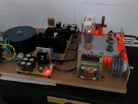
I eventually got the headphone amplifier breadboarded that my first HV shunt was intended for. As a reminder: SE spud using D3A, C3G or E810F (playing right now), vintage Saba opt's and so on...
For testing I initally used a Maida reg at 145V since the Salas' shunt is a bit more ...err... sensitive to prying around with probes, disconnecting and connecting and such
The sonic result wasn't exactly overwhelming (even after burn in) so I put the shunt regulator to use.
 and
and  to Salas again! Don't want to repeat myself too often, but what a difference! The shunt is playing at 75mA for about 42mA consumption at 142V (the lower limit of the trimpot) and beats the Maida by a very comfortable margin... Open, sweet, subtle and authentic... very nice!
For testing I initally used a Maida reg at 145V since the Salas' shunt is a bit more ...err... sensitive to prying around with probes, disconnecting and connecting and such
The sonic result wasn't exactly overwhelming (even after burn in) so I put the shunt regulator to use.
and to Salas again! Don't want to repeat myself too often, but what a difference! The shunt is playing at 75mA for about 42mA consumption at 142V (the lower limit of the trimpot) and beats the Maida by a very comfortable margin... Open, sweet, subtle and authentic... very nice!Attachments
I eventually got the headphone amplifier breadboarded that my first HV shunt was intended for. As a reminder: SE spud using D3A, C3G or E810F (playing right now), vintage Saba opt's and so on...
For testing I initally used a Maida reg at 145V since the Salas' shunt is a bit more ...err... sensitive to prying around with probes, disconnecting and connecting and such
The sonic result wasn't exactly overwhelming (even after burn in) so I put the shunt regulator to use.
Good to know it has served you well in several occasions. Happy listening.
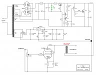
Those bottles are 6D22s halfwave rectifiers... the rest is a very straightforward single tube SE-schematic.
The schematic is now online, shown with the D3A though.. Also bias is now with an orange LED at around 21mA for the E810F.
Not sure about this tube yet, also i am still having a tiny bit of hum on one channel probably due to wiring...
Next in line is C3G which I am using successfully in another headphone amplifier.
are 6D22s halfwave rectifiers... the rest is a very straightforward single tube SE-schematic. The schematic is now online
, shown with the D3A though.. Also bias is now with an orange LED at around 21mA for the E810F. Not sure about this tube yet, also i am still having a tiny bit of hum on one channel probably due to wiring...
Next in line is C3G which I am using successfully in another headphone amplifier.
Attachments
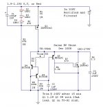
I don't understand this instruction.I should be readable when you fully enlarge it (first zoom it and than extend in lower left corner).
I can expand with the + option.
Then irf9240 and irf240 are just legible. The small text could do with being at least one size larger to help legibility.
I only see a - option after I have used the + option.I found out how.If you hold the arrow on the picture (when you have enlarged it),an other cross comes up,press it and the picture gets even larger.But the picture is quite dissy anyway.
But in Firefox View/Zoom I can blow it up. The text is still too small for clear reading.
Ohh,I thought you used Firefox,I do..But in Firefox View/Zoom
Sure, here it is. I calculated it for more common leds between 1.9V to 2.1V Vf also. Make sure they fall in that voltage bracket, lest is going to go hotter for no reason. Two of them are going to ask for 120mA constant current total, bear that in mind with your power transformer(s) choice. One is enough for 2 channels also if you want to get familiar first. Can't set any lower in mA for preserving all the performance from the HV shunts. Good luck and let us know with some pictures and a report when ready, watch it, it does not forgive misshandling.
Attachments
... watch it, it does not forgive misshandling.
Bwah, I've misused them for some time now and never had to replace a semi
MPSA94 arrived today (at last). Will fire up the irons and build me a nice 2A3 this weekend.

- Home
- Amplifiers
- Power Supplies
- Simplistic MosFET HV Shunt Regs