See posts #3 & # 7 about what does what and how to set it. It is OK to use one trafo and two regs. Better still, use one trafo with double secondaries and two rectifiers. Closer to double mono. There can be many ways of running such tubes. Better read the brand's website or ask Allen Wright so to know exactly. A general third party guess without pointing us to the schematic, would be ''relatively low current, 10-20mA channel total''.
Thanks.
the schematic is here
salas said:
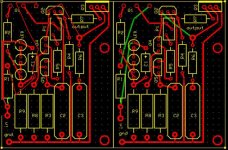
Can you avoid double layer by routing the green traces differently?
I struggled with that and, so, far, am not able to avoid it. Is there a particular advantage to avoiding a double layer?
sesquialtera said:
I struggled with that and, so, far, am not able to avoid it. Is there a particular advantage to avoiding a double layer?
I don't know, cost? Elegance, ease for home etchers? Maybe better usage of the bottom layer as a ground plane than just 3 lines?
Here is a quick idea. I guess feasible if moved to center it again for some very little upper and left side edge clearance.
Attachments
wuffer said:
Thanks.
the schematic is here
I would make one 70-80mA shunt per channel. I don't think that it must be using more than 40mA per channel. So double is safe. If anyone has made this circuit and knows exactly, may tell you. I don't have time these days to look deeper into it, sorry.
I would make one 70-80mA shunt per channel. I don't think that it must be using more than 40mA per channel. So double is safe. If anyone has made this circuit and knows exactly, may tell you. I don't have time these days to look deeper into it, sorry.
Thanks. You have helped me alot
 im very happy
salas said:
I don't know, cost? Elegance, ease for home etchers? Maybe better usage of the bottom layer as a ground plane than just 3 lines?
Here is a quick idea. I guess feasible if moved to center it again for some very little upper and left side edge clearance.
Thanks, Salas, that was brilliant.
One of my big concerns was the possibility of a short with a trace above Q1, but I guess it must be OK...
Still fits on half a board, but only one half shown for clarity.
Attachments
Class time!
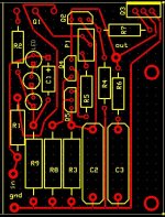
I wanted to offer some pointers on board layout for better performance. Wanting to use to use an example I started moving parts around to improve the layout. I find laying out circuit boards to be a great puzzle. Much more fun than trying to put together jig saw puzzles... You can use the layout I've come up with if you like, tweak on it some more, or just use it for a learning example. The mouting holes are on the far end from the transistors. If the transistors are mounted to a heat sink you only need to support the other end of the board.
With a shunt regulators low output impedance and good high frequency response we need to be carefull of where the signal currents flow on the regulator board. The output loop needs to be as short as possible. Just like you would do star grounding in an amplifier or pre-amplifier, you do the same thing in the regulator layout.The first thing to note on the original layout is that the ground terminal is all the way across the board from the output device (Q3). All the components that are referenced to ground are between the output and ground points and on a small trace to boot. This is not a good thing.Shunt regs work by rapidly changing the current drawn by the output device to keep the output at a fixed voltage. With the long light trace you will have bad ground loops within the regulator. This will limit the performance and posssibly be unstable at high frequencies and or high currents.
The new layout has the circuit broken up into 3 main loops. The output reference loop, the output snubber loop, and the bias loop. The output snubber loop is isolated so that when it is doing it's job at high frequencies the currents will not effect the rest of the circuit. Like wise, the reference loop is as short as possible to help with frequency response and parasitics. The bias loop is all high impedance bias currents that should not have much signal current.
I took the liberties of using 1/4 watt resistors on the gate stoppers to save a bit of space. The rest of the small signal resistors could be swithed over to 1/4 watt also. Check the layout for errors- not having the schematic to match I was not able to link the board and schematic for error checking.
Look over the layout and let me know what you think. Personal preference would have larger pads for Q1 and the wire connections.
Here is the ExpressPCB simplistic.zip file for downloading. Be careful with the file as I did not rename it! Don't want to overwrite your copy...
I wanted to offer some pointers on board layout for better performance. Wanting to use to use an example I started moving parts around to improve the layout. I find laying out circuit boards to be a great puzzle. Much more fun than trying to put together jig saw puzzles... You can use the layout I've come up with if you like, tweak on it some more, or just use it for a learning example. The mouting holes are on the far end from the transistors. If the transistors are mounted to a heat sink you only need to support the other end of the board.
With a shunt regulators low output impedance and good high frequency response we need to be carefull of where the signal currents flow on the regulator board. The output loop needs to be as short as possible. Just like you would do star grounding in an amplifier or pre-amplifier, you do the same thing in the regulator layout.The first thing to note on the original layout is that the ground terminal is all the way across the board from the output device (Q3). All the components that are referenced to ground are between the output and ground points and on a small trace to boot. This is not a good thing.Shunt regs work by rapidly changing the current drawn by the output device to keep the output at a fixed voltage. With the long light trace you will have bad ground loops within the regulator. This will limit the performance and posssibly be unstable at high frequencies and or high currents.
The new layout has the circuit broken up into 3 main loops. The output reference loop, the output snubber loop, and the bias loop. The output snubber loop is isolated so that when it is doing it's job at high frequencies the currents will not effect the rest of the circuit. Like wise, the reference loop is as short as possible to help with frequency response and parasitics. The bias loop is all high impedance bias currents that should not have much signal current.
I took the liberties of using 1/4 watt resistors on the gate stoppers to save a bit of space. The rest of the small signal resistors could be swithed over to 1/4 watt also. Check the layout for errors- not having the schematic to match I was not able to link the board and schematic for error checking.
Look over the layout and let me know what you think. Personal preference would have larger pads for Q1 and the wire connections.
An externally hosted image should be here but it was not working when we last tested it.
Here is the ExpressPCB simplistic.zip file for downloading. Be careful with the file as I did not rename it! Don't want to overwrite your copy...
salas said:The circuits are easy to make. They are variable. I will show 2 voltage scales.
salas said:Keep the constant current source running at least on double the mA that your application circuit needs in steady state. Triple is nicer.
Its all a matter of how big a heat sink you can use. The current used by your audio circuit is not heating the PSU shunt Mosfet. It heats at its most (Vout*CcsIma) when unloaded. The upper Mosfet can hold up to 200V Vin-Vreg. 50V difference is OK to run at its smoothest though, nobody wants to discard more just heating up the P-Mosfet. It heats for Vdif*IccsmA. It can stabilize with just 10V Vdif non the less, but it will be compromised somewhat for transients. R1 sets the CCS current, Iccs=(Vleds-VgsQ1)/R1.
The reg voltage reference is made up by a Wilson (ring of two) CCS feeding a bypassed resistor voltage drop. You can use a fixed R5 or the +trimmer arrangement for a variable shunt. Be careful there not to go beyond 200V Vin-Vout, if you like your nice P-Mosfet alive.
Great performance in practice, tried to keep em practical with easy to source components. 2N6520 is a -350V PNP and KSP94 is an alternative -400V PNP for the higher voltage shunt, as 2SA1625 is. That is if you wanna go to that 360V mark or go to a higher range. The IRF840 works up to 500V.
Regards
Salas
I was just doing a simulation of this circuit in SPICE to make sure I understand how it works. The IRFP9240 is biased by the constant voltage drop across the LEDs to pass, say 100 ma of current if your circuit needs 50ma steady state. The constant current source created by the BCC560s draws a few mA, and the large resistor with the parallel 1uF capacitor locks down the voltage going to the MPSA92 at about a diode drop below the supply. As the current drawn by the load increases, the voltage drop across the 2.2k resistor in the emitter of the MPSA92 will decrease, causing the IRF840 to conduct less and keeping the current through the circuit, thus the supply voltage constant. Vice versa for a load current decrease. The resistor and capacitor in series prevent oscillation due to the negative feedback. Does that sound about right?
Re: Class time!
Thanks Gary for helping the PCB for the people. I only do P2P with hardwired sub star grounds etc so I would never develop and test a recommended PCB. I have read your concepts about the layout and I agree. Regards.
Gary P said:I wanted to offer some pointers on board layout for better performance.
Thanks Gary for helping the PCB for the people. I only do P2P with hardwired sub star grounds etc so I would never develop and test a recommended PCB. I have read your concepts about the layout and I agree. Regards.
Re: Class time!
And maybe Q1 not so close to Q2? Its better to spread the heating points on the sink.
Personal preference would have larger pads for Q1 and the wire connections.
And maybe Q1 not so close to Q2? Its better to spread the heating points on the sink.
...and the large resistor with the parallel 1uF capacitor locks down the voltage going to the MPSA92 at about a diode drop below the supply...The resistor and capacitor in series prevent oscillation due to the negative feedback. Does that sound about right? [/B]
Actually the current that goes to that resistor is already ''locked'' by the ring of two CCS through the resistor. Thus the resistor's voltage drop is our voltage reference for the regulator.
There is no loop feedback. Its a Zobel that just smooths the ringing by termination.
salas said:
There is no loop feedback. Its a Zobel that just smooths the ringing by termination.
It makes quite an impressive difference on the simulation, that's for sure.
Hi Salas
Got all the parts, and has been arrange it PTP like the Gary's Layout.
i got question about the tube rectifier EZ81. does this shunt reg retain the claimed benefits of the tube rectifier, such as warm sounding? if not, i would rather just use the sckottky diode that i have in my drawer. it rectify more spare voltage as well that i can have the spare 50v as you recommend.
should i go with tube rectifier or solid state rectifier?
thx in adv
erwin
You can still hear the tube rectifier but to about the 20% the impact it would normally have with a passive CLC.
I would rectify both ways and see what happens in a particular system VS the particular tube rectifier. But only by keeping the 50VDC difference in all cases. If you cant have the 50V, go solid state.
I would rectify both ways and see what happens in a particular system VS the particular tube rectifier. But only by keeping the 50VDC difference in all cases. If you cant have the 50V, go solid state.
hi Salas
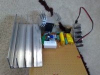
nice.. i got some heatsink confusion. attached the picture of several heatsink i got. can i use the smallest one on the irfp9240? the other one is cpu heatsink with fan. then the other one is for 2n3055. thx in advance
thats the board that i arrange with Gary's suggestion layout. haven't soldered them in. but should be find as i am going to prove read it again before soldering.
erwin
Attachments
- Home
- Amplifiers
- Power Supplies
- Simplistic MosFET HV Shunt Regs