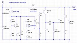
I have finally gotten the HV shunt regulator working very well, but with some interesting changes to the original Salas' design. The end result became a part Salas' and part something else. The process of development has been long and very educational one. I initially started out with the original Salas' design and eventually arrived to this one which addressed several of my previous concerns. I am not sure if I should post the schematic here, but if some of you could kindly check the Zo of this circuit for me will very much appreciated. I have not been able to locate a LTSpice model for IXCP10M45S and the ZTX558.
Attachments
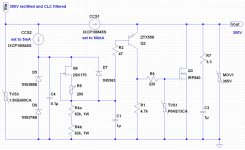
Hi. Your concerns were to use a higher hfe, lower Cob driver, give to the ref Jfet 10V VDS bracket, also break it away from the driver's Vbe tempco I suppose. I will try to look for the models at a point for you, but it would simulate with equivalents closely enough non the less. I would expect it not to change its original trend for Zo since the only change as for the whole parallel Vref & power handling is the use of another driver BJT. Should be a bit better with that part. The depletion mode CCS IXYS parts have to do with input isolation figures, not affecting Zo. I would recommend you Supertex DN2540 there if you can get any, for better results even. I see the use of Zeners to define the working space for the Jfet, not good from a noise point of view though. You can not set less Vo than ZenersTot-K170's Vmax (D7) in this arrangement also, but its no concern if its a planned application reg. Where is it applied and what did it substitute by the way, did it help noticeably? Comprehensive & working tweaks are nice. Congrats.
Salas,
Thanks for your comments.
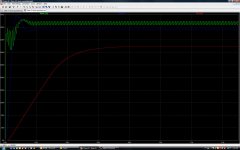
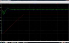
I was able to run a simulator using some equivalent model. The picture on the left showing the circuit behavior of the original Salas's design. The picture on the right showing the simulation of my tweak. Q4 behaved more like a CCS now.
The main reason for all my changes was that adaptation of IXCP10M45S created instability in the whole circuit. That have resulted in destroying a whole bucket of Q3. As bad as it may be, I happened to have many of this IXYS devices sitting around so I may as well make good use of them. Unfortunately, DN2540 is extremely hard to come by in where I live.
This Reg is intend to feed a Aikido line-level pre-amp. Its total idle current is about 18mA @ 300V. The Shunt Reg is to replace the original tube based series reg.
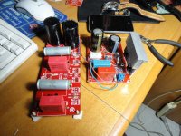
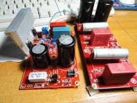
Will post some photos of it later.
Thanks for your comments.
I was able to run a simulator using some equivalent model. The picture on the left showing the circuit behavior of the original Salas's design. The picture on the right showing the simulation of my tweak. Q4 behaved more like a CCS now.
The main reason for all my changes was that adaptation of IXCP10M45S created instability in the whole circuit. That have resulted in destroying a whole bucket of Q3. As bad as it may be, I happened to have many of this IXYS devices sitting around so I may as well make good use of them. Unfortunately, DN2540 is extremely hard to come by in where I live.
This Reg is intend to feed a Aikido line-level pre-amp. Its total idle current is about 18mA @ 300V. The Shunt Reg is to replace the original tube based series reg.
Will post some photos of it later.
Attachments
Sometimes up to 2K2 gate stopper is used for the IXYS. But I guess you did that too. Having more VDS and a second CCS fed Vref to provide it, gives a steeper regulation curve no doubt, but using Zeners to establish that, still bugs me a bit noise wise. The steepness knee has to do its ''voicing'' too. Can you sim the original with a no trimmer J201 instead of a K170 and a circa 540K Voltage reference resistor R4? Lets see the curve for that also, since its an alternative Jfet for Q4. Although could be limper even towards DC.
Hi Salas,
so far smooth sails. I've tweaked the BAS CRCR to 224.7V and wired it to the SSHV (QH PCB). I'm using 82uF 400V for C5 since that is what I have on hand.
I adjusted trim to 208.7V with 5K load resistor. My question is how long do I need to wait for it to stabilize? I see voltage increasing in small increments.
I will try 1/2hr and see if it keeps going up or eventually settles.
maybe mine takes longer to stabilze because of the 6x5GT rectifer in the bas psu?
will hookup the aikido and do a listen on the weekend
Thanks!
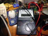
My HP Voltmeter reads 1uV AC on the output of the SSHV. Pretty amazing, never read anything so low for a high voltage output. usually in the mili volts.
Looking foward to hearing how it sounds.
Wow, 1uV is amazingly low. What's the bandwidth and sampling rate of your HP voltmeter? I presume it is a digital true rms meter.
My HP Voltmeter reads 1uV AC on the output of the SSHV. Pretty amazing, never read anything so low for a high voltage output. usually in the mili volts.
Looking foward to hearing how it sounds.
Congrats, 1uV is indeed great performance. What model voltmeter did you use?
HV to LV shunt regulator
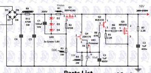
Due I had an unused pcb of HV shunt regulator (by Quanghao) I wonder if was possible to transform the HV to LV as powesupply of a Pass B1 buffer at 18V.
Yes, it's possible, and Salas suggest what to modify: see schematic
It works perfectly!!!
Thanks Salas!!!
Due I had an unused pcb of HV shunt regulator (by Quanghao) I wonder if was possible to transform the HV to LV as powesupply of a Pass B1 buffer at 18V.
Yes, it's possible, and Salas suggest what to modify: see schematic
It works perfectly!!!
Thanks Salas!!!
Attachments
Sometimes up to 2K2 gate stopper is used for the IXYS. But I guess you did that too. Having more VDS and a second CCS fed Vref to provide it, gives a steeper regulation curve no doubt, but using Zeners to establish that, still bugs me a bit noise wise. The steepness knee has to do its ''voicing'' too. Can you sim the original with a no trimmer J201 instead of a K170 and a circa 540K Voltage reference resistor R4? Lets see the curve for that also, since its an alternative Jfet for Q4. Although could be limper even towards DC.
Sorry Salas, I have been very busy with other stuffs. Anyway, I couldn't find a LTSpice model for J201. What do you think about the noise performance on this change, then?
Attachments
- Home
- Amplifiers
- Power Supplies
- Simplistic MosFET HV Shunt Regs