Don't expect me to start debugging people's configurations if it will not play with some loads or settings. I have even seen talk about putting chokes in series and splitting after the reg. Yeah, that will be the day for its Zo or stability.
I say you fill up your fridge with beer
 Fun times ahead!
. Don't expect me to start debugging people's configurations if it will not play with some loads or settings. I have even seen talk about putting chokes in series and splitting after the reg. Yeah, that will be the day for its Zo or stability.
I thought people were running stereo with a single reg, or is this unproven territory?
I thought people were running stereo with a single reg, or is this unproven territory?
I did try stereo with a single reg, split after choke to two regs and dual mono. All these configurations worked in my case, but the dual mono was sounding better, subjectively speaking.
The IRF840PBF is only 95 cents at Mouser vs $5 for the IRF840, is it OK to sub?
http://www.mouser.com/catalog/specsheets/91070irf.pdf
http://www.mouser.com/catalog/specsheets/91070irf.pdf
I did try stereo with a single reg, split after choke to two regs and dual mono. All these configurations worked in my case, but the dual mono was sounding better, subjectively speaking.
All those configurations were with shunt regs?
I thought people were running stereo with a single reg, or is this unproven territory?
Yep, but not with added stuff AFTER the reg.
Yep, but not with added stuff AFTER the reg.
Like adding what?
Choke filters split.
Doesn't adding chokes after the regulator detoriates Z Out?
Before, Joshua, before.
AC>Bridge>1st cap>2 chokes>two 2nd caps>two regs>two loads
Is there any way to model a split supply for the prefilter like this in PSUD ?
Is there any way to model a split supply for the prefilter like this in PSUD ?
Not that I am aware of.
Perhaps one way would be to add a constant current generator at the point of the split to represent the second (absent) channel. Everything before that point would be the shared components, and everything after would be single channel.
Might work.
Not that I am aware of.
Perhaps one way would be to add a constant current generator at the point of the split to represent the second (absent) channel. Everything before that point would be the shared components, and everything after would be single channel.
Might work.
Great idea thanks
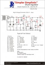
The circuit above has been checked enough, its stable, and it can go over 300V if the MJE350 is substituted with a proper PNP driver transistor like the 400V MPSA94 etc. R3 should be 82K & R4 220K in an over 300V application. The MJE is better if you target lower than 300V. The higher resistive load (R5) on the error amp than what I usually practiced, saves in driver BJT's heat and helps its stability in higher voltages without any performance penalty. Sometimes I use optional protective Zeners for added mishandling safety. Not strictly necessary though. Just use D1, does most safety. 15V DC IN-DC OUT is the lower limit for adequate performance. No less than 20mA must be left running in the shunt on top of what the load demands. Here is it again showing the proper application of safety Zeners. Also a point 2 point example of mine in the second picture.
Hi Salas!
I would like to use this schematic for my low voltage preamp, it is need 130-140V/50mA to operate. Could you guide me how to get those voltage, ex +135VDC out with 250VDC after regulate
Thanks!
Thanks a lot!
One more question.
I can't get IRF9610 and IRF840 at local shop, they are only have IRF9620 and IRF740.
Can I use IRF9620 and IRF740 to replace for IRF9610 and IRF840?
I've read the datasheet all of them, but I am not sure, cos they have some differences features, example: IRF840 VDS=500V; ID=8A; rDS=0.85ohm while IRF740 VDS=400V; ID=10A; rDS=0.48ohm.
I would like to ask about some high wattage resistor types , which should be used in the HV shunt.( in 300 V , out 250V )d
I know there was sugestion to use carbon resistors for R2 ; R6; R9 as gate / base stopers - if I understand correctly it should be carbon composition because of the low inductance ( what about the noise ?)
But what about R3 ; R4 ; R5 ? Normaly I would use low noise , non inductive wire wound but here comes the voltage limitation.
Other solution would be film type non indutcive ( MP930 Caddock )
- but they cost a lot of $$$ and hard to find in all needed values
Attachments
Thanks a lot!
One more question.
I can't get IRF9610 and IRF840 at local shop, they are only have IRF9620 and IRF740.
Can I use IRF9620 and IRF740 to replace for IRF9610 and IRF840?
I've read the datasheet all of them, but I am not sure, cos they have some differences features, example: IRF840 VDS=500V; ID=8A; rDS=0.85ohm while IRF740 VDS=400V; ID=10A; rDS=0.48ohm.
They will most probably work, but I have never used them to know if they will show any allergy.
- Home
- Amplifiers
- Power Supplies
- Simplistic MosFET HV Shunt Regs