Hi Salas,
Will it has adverse effect to the overall performance (in term of output impedance) of the your shunt regulator design if I add a 330-ohm resistor between the output rail and the emitter of Q2?
My concern is that Vds of Q4 (2SK170) is being clamped by the Vbe of Q2 (2N6520) to around 0.4-0.7V. Although the saturation voltage for Q4 can be very low according to the datasheet, in actual pratice R8 drops some voltage while point-to-point connections can also drops some voltage. That will leave not much room for Q4 to maneuver. In the worse case, voltage reference developed by Q4 and R4 can become non-functional if actual Vsat of Q4 is higher than the specification.
Attachments
Whatever you put there to lift Vbe, be it a Led or a resistor will have a degeneration effect that will lower the loop gain progressively well in the pass band, thus a heavy direct hit on output Z will be suffered. The only reason to lift, would be if restricted to only higher -Vto NJFETs. In that case the lift MUST be bypassed with a large electrolytic. 2SK170's -Vto is about -0.5V, thus when under even +0.5V the performance 2X pinch off rule of thumb is satisfied. Proof is that it works well for enough builders. Never ever a 2SK170GR or BL, failed to produce current under Vbe margin. Don't worry. What you SHOULD do for the higher voltage circuit is make the 2k2 R5 a 5k6. In the light of recent experience, an Italian builder had problems with the driver NPN's dissipation and we solved it by using 2 in cascode so to cut their heat in half. A higher load resistor has analogous effect by dropping the current across the BJT, plus it ups the loop gain enough. -400V PNPs are sort in hfe.
Nothing really, you just supply the reg with 280, and you arrange the current in the CCS via R1 choice so to have at least 20mA spare running on amp's peak demand. That is double its bias for a push pull class A more or less. The provision will be mainly to adequately sink all that heat coming from the shunt current when playing low, the reg will be hot enough even when playing high, given the most music's low average to peak percentage. Maybe by monitoring the load current over some 0.1R for average and high volumes someone can determine two R1s and ''change gear'' with a switch depending on use and helping save sinking area and the polar bear. The values in the example schematic lend themselves to enough scaling above or below the noted current and voltages.
Attachments
Recap
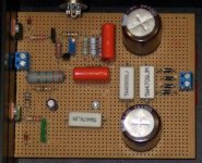
The circuit above has been checked enough, its stable, and it can go over 300V if the MJE350 is substituted with a proper PNP driver transistor like the 400V MPSA94 etc. R3 should be 82K & R4 220K in an over 300V application. The MJE is better if you target lower than 300V. The higher resistive load (R5) on the error amp than what I usually practiced, saves in driver BJT's heat and helps its stability in higher voltages without any performance penalty. Sometimes I use optional protective Zeners for added mishandling safety. Not strictly necessary though. 15V DC IN-DC OUT is the lower limit for adequate performance. No less than 20mA must be left running in the shunt on top of what the load demands. Here is it again showing the proper application of safety Zeners. Also a point 2 point example of mine in the second picture.
*A calculator by member ''Lazybutt'' FRED was posted on 14/1/12 and is added here. Has explanations, and its about helping you to configure.
Attachments
Sims
Here is how it simulates. Good stability margin, nice enough PSRR, and about 10 mOhm Zo, that does better the more we overspec current and heat. But don't sweat it, cabling is going to dominate on Zo. Of course those are just the trends, usually is worse enough for numbers in real life. The concept has been used by enough people reporting in this thread since its inception with some variation up to now. Seems like accepted as balanced enough between simplicity, relative performance, and popular subjective commentary. Thanks for your participation.
Here is how it simulates. Good stability margin, nice enough PSRR, and about 10 mOhm Zo, that does better the more we overspec current and heat. But don't sweat it, cabling is going to dominate on Zo. Of course those are just the trends, usually is worse enough for numbers in real life. The concept has been used by enough people reporting in this thread since its inception with some variation up to now. Seems like accepted as balanced enough between simplicity, relative performance, and popular subjective commentary. Thanks for your participation.
Attachments
Hi Salas,
The protection Zener D5 added on your last posted schematic, will it also work for about 30 Volt DC Out?
D5 & D6 are for transients by mishandling. Work for any Mosfet regardless of the circuit's DC levels, its for avoiding gate punch through. D1 is a 150V 5A Zener so to protect the CCS Mosfet when there is potential to see over 200V (its max spec), say in an accidental swift short. If your DC In is not over 200V in the first place, that Zener is redundant. That said, there are many examples of finely working Simplistic Regs in this thread for a long time without Zeners. Its for when plugging or unplugging carelessly or tweaking, recycling on/off etc. Just to know how to apply.
D5 & D6 are for transients by mishandling. Work for any Mosfet regardless of the circuit's DC levels, its for avoiding gate punch through. D1 is a 150V 5A Zener so to protect the CCS Mosfet when there is potential to see over 200V (its max spec), say in an accidental swift short. If your DC In is not over 200V in the first place, that Zener is redundant. That said, there are many examples of finely working Simplistic Regs in this thread for a long time without Zeners. Its for when plugging or unplugging carelessly or tweaking, recycling on/off etc. Just to know how to apply.
I wonder about the necessity of D6, since IRF840 has maximum VDSS of 500 Volt.
You probably mean D5. The gates have an oxide layer that has about 20V max before they become Swiss cheese. Don't mix it with VDS max.
Indeed, I meant D5. If VDS Max. is 20V, then 150V Zener is as good as no Zener at all. May be it takes 18-19 Volt Zener?
No worries. Essentially D1 may only be called for in real reg use anyway. 99% it is all protection it might come handy. D5 and D6 could be called for mainly when testing with probes. Fully deployed gate protection takes 2 at each gate, one towards negative too. Was just an example.
Salas, in your last Simpler Simplistic schematic, safety diodes aside, you added R10 (47 ohms) and change Q1 from IRFP9240 to IRF9610.....
What's the role of R10 and why a smaller Pmos now?
I remember since LV Simplistic Shunt you were always in favour of beefy TO247 mosfets over smaller TO220s.
What's the role of R10 and why a smaller Pmos now?
I remember since LV Simplistic Shunt you were always in favour of beefy TO247 mosfets over smaller TO220s.
R10 helps the cap even out the performance in the VLF without making the component value big. I wanted to make it full TO-220 since its only few mA in HV and IRF840 is TO-220 already, and see if it holds. I tested it and it does. For same mounting in both elements, cheaper and faster part.
- Home
- Amplifiers
- Power Supplies
- Simplistic MosFET HV Shunt Regs