If the PT is sufficient: larger voltage than 250VAC at desired load.I gues are you suggesting CLC right?
If not, only SS rectification helps.
!!!!!If the PT is sufficient: larger voltage than 250VAC at desired load.
If not, only SS rectification helps.

Understood only SS bridge rectification.!!!!!
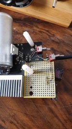
Well, a development, while in the process of populate the auxiliar perforated board, to complete a parallel cascode shunt supply. An idea come to my mind, I leave the thing incomplete, and instead I place another Q2, the unique current limiting part, and use the same beloved high speed IXTP02, just below on the pcb downside using a row three pin as a socket. On the test bench a parallel only Q2 to the SSHV2 achieves twice the current, so it reach my need theoretically. But how about the sound? Much better, the music floats from anywhere or from everywhere, pure natural music flow that makes impossible to tolerate again the single transistor shunt.
I want to mention, since this configuration is powered up, the circuit breaker protection on the AC mains filter module has breakdown the system two times in one hour. Maybe just coincidence but I wanted to mention.
I want to mention, since this configuration is powered up, the circuit breaker protection on the AC mains filter module has breakdown the system two times in one hour. Maybe just coincidence but I wanted to mention.
Attachments
Last edited:
Be care for Jordi is high voltage & can kill you!!!!Well, a development, while in the process of populate the auxiliar perforated board, to complete a parallel cascode shunt supply. An idea come to my mind, I leave the thing incomplete, and instead I place another Q2, the unique current limiting part, and use the same beloved high speed IXTP02, just below on the pcb downside using a row three pin as a socket. On the test bench a parallel only Q2 to the SSHV2 achieves twice the current, so it reach my need theoretically. But how about the sound? Much better, the music floats from anywhere or from everywhere, pure natural music flow that makes impossible to tolerate again the single transistor shunt.
I want to mention, since this configuration is powered up, the circuit breaker protection on the AC mains filter module has breakdown the system two times in one hour. Maybe just coincidence but I wanted to mention.
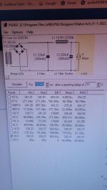
As a power diode bridge, I'm using "TEA2209DB1584 active bridge rectifier demo board" but assembled by myself, this means average solder joints (high-power transistors, although smd types are thick and difficult to weld) the PCB board is also very thick. When I assemble the next prototype, I will also put all the super small smd capacitors, now I see that they are necessary.
The fact is that the diode bridge has a large effect in the final sound of the field coil speaker. Specifications shouldn't be a problem, high enough. But I still haven't gotten the right montage.
Correct Salas, I made a parallel with Q2 to the right of the Q2 pins. (Two parallels IXTP02N) Can there be any downsides? Can I go out this way? sound is good, veery good!
Edit, now I find all transistors (one Q1 and two Q2) fully blown up, so I start thinking this failure cause also damage on diode bridge.
Last edited:
Whenever you parallel MOSFETs for more current you increase their capacitance. The same happens internally due to larger silicon design if with a higher power single. But the cascode's job beyond taking most of the voltage and dissipation is not to let pF multiply with the gain. Keeping basically to Ciss plus twice the Crss spec.
- Home
- Amplifiers
- Power Supplies
- Simplistic MosFET HV Shunt Regs