Salas,
This is my second implementation of the SSHV and I am one happy customer! In this case, this dac with a grounded amplifier tube output had a few mV of AC on the output. Which was not audible unless the gain on the line stage was increased to maximum. However, I run my linestages wide open and use digital volume. Well, that meant that I had to get rid those few mVs.
The dacs HV reg is a simple C-zener controlled emitter (TIP50)-C. Basically a pi filter with the zener and TIP50 in between the two caps. That was fine as long as you had a volume pot between the dac and the linestage.
Now, I have a wide open gain structure and zero noise. The DACs idling output noise went from millivolts to microvolts.
The tube output is now solid state in its noise structure, which is really amazing and is essential for source devices.
Thanks for the design and thanks to Tea for the great kits!
What we really need now is an HV reg that can handle a few hundred milliamps......

higher power type
How would you do this for 75W or 300mA, 400v to 300v?
best Barry
Hi.And the higher example.
How would you do this for 75W or 300mA, 400v to 300v?
best Barry
Hi.
How would you do this for 75W or 300mA, 400v to 300v?
best Barry
I don't have such a shunt design.
Hi
What would you suggest here, I have 275V 400mA (300v unloaded) Transformer the transformer gives 403V DC unloaded, so PP Amplifier is 400V, I need 300-310V. I can't see dropper resistors working too well in this application
I do have your Regulators in my Preamp!
regards
Barry
What would you suggest here, I have 275V 400mA (300v unloaded) Transformer the transformer gives 403V DC unloaded, so PP Amplifier is 400V, I need 300-310V. I can't see dropper resistors working too well in this application
I do have your Regulators in my Preamp!
regards
Barry
Hmm... Maybe a capacitance multiplier with Zeners reference at 300V could take it due to its series and does not dissipate own reserve bias. But 100V drop across it is still a big waste when not using the proper transformer. Will certainly burn up to 40W at max peak if the amp can actually pull those 400mA from the transfo. It would help much with ripple filtering, not sure if you will prefer it to a proper voltage raw DC output stage supply in the dynamics department. But simple enough a circuit concept to try and decide.
So I had some time today to revisit my build and unfortunately still cut get it work right. I added more C and not have full wave CRC arrangement with 100uf-100R-470uf. Here are some numbers I measured:
Vac_in = 118V
No load:
Vac _out =239V
Vdc_in no load =346V
With the regulator plugged:
TP = 300mV
Vac _out =239V
Vdc_in = 308V
Vdc_out = 300V
If I crank TP voltage (I) up:
TP=540mV and doesn't go higher
Vac_out = 230V
Vdc_in = 293V
Vdc_out = 293V
If keeping all the same I trim Vdc_out down to lower values like 270V
then the sag drops and V at TP goes to ~800mV on its own.
I honestly have no idea what to do next...
I got bigger heatsink for Q3, its temperature seems fine now. When the trim pot is fully "open" I get 800mV reading at the TP and it goes down to 520mV after Q1 and Q2 are fully warm. They are warm, not hot for sure. All the transistors are from the GB, so I did not measure Vgs, assuming they should be good.
Actually I take it back, even with my pretty big heatsink the temperature of the Q3 on it is way to hot after 40mins, I'd say 70+.. Q1 and Q2 are slightly warm and the TP shows 560mV maxing out the trim. Aikido is plugged and consuming 19mV per channel @ 310V
Just to make sure as I found in a data sheet G and S are left and right pins. So on Q1 it starts at 2V and drops rapidly to 1.1V and Q2 starts at 1.2V and drops to 1V. I would not wait longer as Q1 was without a heatsink as it is the only way I could get to pins and measure.
Big picture, just in case I am missing smth...
That explains it. If Vgs Q1 stayed, Q2 would have more voltage envelope and the cold CCS mA setting would be nearer to the warm setting. Maybe Vin (Raw DC) drops enough and Q1 conducts less? How much Vin - Vout DC difference is there across the regulator when cold vs when everything has warmed up? When using the Q1's sink as well.
Sag in your raw DC arrangement? Examples like marginal transformer's secondary AC voltage for the purpose, lower PIV than adequate bridge that lost an internal element, too small a filter cap? Can't give the demanded constant current mA while staying put for some reason.
If that wasn't happening before maybe a problematic MOSFET in the reg? Static electricity can punch them while simply handled or soldered sometimes. Does Q3 show healthy 3-4V Vgs?
Wires not well screwed in the Raw DC mini board? Too much AC ripple on the 100uF cap steals valuable DC component? Needing more uF? That filter cap has developed much ESR?
Full bridge rectification derates 40% from a transformer's AC rated current for DC. But yours still rated high enough for the purpose. CCS can be tough on transformer regulation losses too.
There's progressive sag in your raw DC with the more CCS loading. Got to scope it and see where the sag starts, at what part of the pre-filter, and how much is AC ripple in the raw's last capacitor. Can there be a bad rectification diode? Also to see if there is possible oscillation in the main reg. Up the gate resistors for Q1 Q2 to 1k if in doubt. Plus make sure that every semiconductor in it still shows healthy Vgs or Vbe with the DMM. Sinks must not feel saturated from heat as well. Is there a picture of the incorporated regulator's section in your combo build?
I do not have a scope, I will see if I can get something to work with sound card and scope software. I see you can use Dayton audio DATS woofer tester as a scope, maybe that will work... How would I measure high voltages with this type of tools, a voltage divider?
The bridge measures fine with DMM, all transistors as well. I also have parts to make another regulator, that can help to reduce a probability of regulator parts being bad...
At this point I have it feeding into a 10k resistor. Btw, can it be due to the resistor as ~300V at 10k gives me that ~30mA?
The bridge measures fine with DMM, all transistors as well. I also have parts to make another regulator, that can help to reduce a probability of regulator parts being bad...
At this point I have it feeding into a 10k resistor. Btw, can it be due to the resistor as ~300V at 10k gives me that ~30mA?
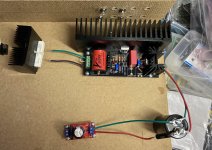
Attachments
i just received two SSHV2 kits from Monsieur Tea-Bag (thanks very much to Tea-Bag for the quick service).
Planning on using one to upgrade the separate-chassis power supply for my "PhonoDude" 5755/5751 (or 6N3) phono preamp (a very pleasant Dutch design that's now "gone commercial" to the tune of ~1600 Euros; should have built TWO).
Maybe use the other one for my mono DHT "FlexiAmp" (45/2A3/300B/46 fixed bias on a little chassis, with 417A driver and regulated DC fils).
Is there consolidated documentation somewhere for the SSHV2?
Or should I just read this enormous thread, starting with Salas' introduction, and make notes for my particular application as I piece through it?
For example, there are several substitutes for the DN2540 mentioned in the thread, but no documentation tabulating specs and pros & cons. Likewise, heat-sinking solutions...
For another example, it isn't clear to me the relationship between S0/S+ and F0/F+ outputs. The Build Guide says to apply test load between S0/F0 and S+/F+, and that "all four wires should be used always" and that after calibration, to "twist together S wires and F wires in Force and Sense pairs."
Whoa, what? I ain't stupid exactly, just a little simple. I'm sure the answers are buried in the thread, once I piece them together. But I'd hate to do that, only to discover that Timmy in Pleasantville has written the Dummies Guide to the SSHV2.
As a mere Mechanical Engineer, I'm tempted to mention something about the Bauschinger Effect or Luders Lines so you EE folks can appreciate my confusion...
Related Story: I worked with our CFD (Computational Fluid Dynamics) software vendor for over a decade, giving papers, consulting with their design & marketing folks. Had to constantly remind them that folks that KNEW they NEEDED the product had already BOUGHT it.
Using SSHV2 on my tube phono
Hi guys,
Hope all is fine.
Just one quick question, I am building new phono amp, based upon 4 C3G tubes and 4 Lundahl IS transformers. The power supply is CLC around 230VDC, and I am looking for something around 180VDC to 200VDC, with 35-40mA.
I have a built not used SSHV2 board, what would be the benefits of using it on my circuit, instead of the normal CLC arrangement?
May I use the normal star ground, as the “one point” ground for the all circuit?
Sorry to bother you all with this, but your experience and inputs are very welcome.
Thanks, take care, and be safe.
Happy building 😁
Is there consolidated documentation somewhere for the SSHV2?
Or should I just read this enormous thread, starting with Salas' introduction, and make notes for my particular application as I piece through it?
For example, there are several substitutes for the DN2540 mentioned in the thread, but no documentation tabulating specs and pros & cons. Likewise, heat-sinking solutions...
For another example, it isn't clear to me the relationship between S0/S+ and F0/F+ outputs. The Build Guide says to apply test load between S0/F0 and S+/F+, and that "all four wires should be used always" and that after calibration, to "twist together S wires and F wires in Force and Sense pairs."
Whoa, what?
Main doc is the pdf guide. Has all the essential info to build. There is also a troubleshooting discussion link in post #1.
Don't substitute the DN2540s if there is no extra voltage or power reason. There are higher voltage and/or higher current IXYS DMOS types that usually work but they are also slower i.e. more capacitive. Compromising the CCS impedance vs frequency spec.
Force and Sense are the F and S points that comprise the output. F wires carry power to the load S wires sense the load's nodes. Its called remote sensing and nulls the main F wires resistance effect. All wires should be connected to work at all.
Hi guys,
Hope all is fine.
Just one quick question, I am building new phono amp, based upon 4 C3G tubes and 4 Lundahl IS transformers. The power supply is CLC around 230VDC, and I am looking for something around 180VDC to 200VDC, with 35-40mA.
I have a built not used SSHV2 board, what would be the benefits of using it on my circuit, instead of the normal CLC arrangement?
May I use the normal star ground, as the “one point” ground for the all circuit?
Sorry to bother you all with this, but your experience and inputs are very welcome.
Thanks, take care, and be safe.
Happy building ��
Hi
You may use a star ground no problem. About opting for active regulation or not its something you have to objectively and subjectively compare in your build. If the noise floor gets better or what tone you prefer. One thing is its a usually cheaper solution than employing quality chokes.
SSHV2 Proximity to Load
An early post (I’ve lost it now...) suggested that the SSHV2 should be wired “as close as possible” to the load”.
My preamp candidate for the SSHV2 uses a remote power supply with an 18-24” cable connection between the little C-L-C p/s and the preamp. Haven’t worked out the loads yet, but they’re likely extremely small.
(a) how far is Too Far between SSHV2 and Load?
(b) what determines this? Capacitance of the wiring? Inductively sucking stray currents out of the ether? Something else?
(c) does this depend on load?
- Home
- Amplifiers
- Power Supplies
- Simplistic MosFET HV Shunt Regs