So I powered up the regulator and everything looks solid and stable (I even found 10uf cap ") . One question, Maida regulator that I am replacing states it can deliver up to 50mA (powering Aikido), should I just set up HV2 reg to do the same? Pretty excited to listen to it as L-adapter for heaters cleaned things up quite a bit!
. One question, Maida regulator that I am replacing states it can deliver up to 50mA (powering Aikido), should I just set up HV2 reg to do the same? Pretty excited to listen to it as L-adapter for heaters cleaned things up quite a bit!
. One question, Maida regulator that I am replacing states it can deliver up to 50mA (powering Aikido), should I just set up HV2 reg to do the same? Pretty excited to listen to it as L-adapter for heaters cleaned things up quite a bit!Whatever is the real consumption of the client circuit plus 20mA spare is the setting goal. What can be delivered by another regulator as max spec maybe it does or does not represent what is really consumed by the client circuit after its start up. If there is a power on consumption surge the current limiter in the SSHV2 will moderate it anyway.
Best is to measure consumption as it is made now with a DMM mA meter mode in series at B+ after the other reg. Much spare capacity quickly turns into substantial needless heat in a shunt.
Best is to measure consumption as it is made now with a DMM mA meter mode in series at B+ after the other reg. Much spare capacity quickly turns into substantial needless heat in a shunt.
So I fired it up today and everything works, but I have a couple of questions:
1. I use 80x60x20(8mm base) heatsink, Vin is 335 and Vout is 310 and the heatsink is probably 65-70C (can hold my hand for 5sec most, battery is dead in the thermometer sorry). So I guess bigger heatsink is a must.
2. Current setting. When the regulated is powering the device, what TP readings would show, the drain by the preamp?
Before swapping the regulator I measured how much current the preamp uses and it way 15mA per channel, so 30mA in total. @300V it gave me 10K 10W resistor. I used that resistor to set up 600mV at the test points(just to have some extra room). The resistor was super hot btw. Now when I measure at the TP I read 410mV, and the preamp draws ~18.5mA, but I also changed input tubes: 6SN7->6SL7 to get more gain.
Does it sound reasonable to you? Thank you.
Attachments
Last edited:
The heatsink seems rather small indeed.
The T.P. reading indicates the CCS current you set. The total mA available before current limiting kicks in. It does not measure what part is going to the load. You should had set 50mA (500mV TP) in the first case. Be conservative with spare. 10mA less is 3W less at 300V. The 410mV indication shows 41mA current limit. For 18.5mA load (total for two channels) 41mA is reasonable.
The T.P. reading indicates the CCS current you set. The total mA available before current limiting kicks in. It does not measure what part is going to the load. You should had set 50mA (500mV TP) in the first case. Be conservative with spare. 10mA less is 3W less at 300V. The 410mV indication shows 41mA current limit. For 18.5mA load (total for two channels) 41mA is reasonable.
I got bigger heatsink for Q3, its temperature seems fine now. When the trim pot is fully "open" I get 800mV reading at the TP and it goes down to 520mV after Q1 and Q2 are fully warm. They are warm, not hot for sure. All the transistors are from the GB, so I did not measure Vgs, assuming they should be good.
Actually I take it back, even with my pretty big heatsink the temperature of the Q3 on it is way to hot after 40mins, I'd say 70+.. Q1 and Q2 are slightly warm and the TP shows 560mV maxing out the trim. Aikido is plugged and consuming 19mV per channel @ 310V
Actually I take it back, even with my pretty big heatsink the temperature of the Q3 on it is way to hot after 40mins, I'd say 70+.. Q1 and Q2 are slightly warm and the TP shows 560mV maxing out the trim. Aikido is plugged and consuming 19mV per channel @ 310V
Last edited:
Just to make sure as I found in a data sheet G and S are left and right pins. So on Q1 it starts at 2V and drops rapidly to 1.1V and Q2 starts at 1.2V and drops to 1V. I would not wait longer as Q1 was without a heatsink as it is the only way I could get to pins and measure.
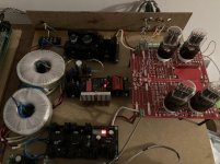
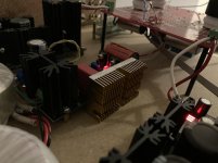
Big picture, just in case I am missing smth...
Big picture, just in case I am missing smth...
Attachments

Last edited:
That explains it. If Vgs Q1 stayed, Q2 would have more voltage envelope and the cold CCS mA setting would be nearer to the warm setting. Maybe Vin (Raw DC) drops enough and Q1 conducts less? How much Vin - Vout DC difference is there across the regulator when cold vs when everything has warmed up? When using the Q1's sink as well.
Sag in your raw DC arrangement? Examples like marginal transformer's secondary AC voltage for the purpose, lower PIV than adequate bridge that lost an internal element, too small a filter cap? Can't give the demanded constant current mA while staying put for some reason.
If that wasn't happening before maybe a problematic MOSFET in the reg? Static electricity can punch them while simply handled or soldered sometimes. Does Q3 show healthy 3-4V Vgs?
If that wasn't happening before maybe a problematic MOSFET in the reg? Static electricity can punch them while simply handled or soldered sometimes. Does Q3 show healthy 3-4V Vgs?
50VA@240V secondary, 1000V bridge 100uf 450V cap, gives 360V with no load. Q3 Vgs -- 3.5V. I usually pretty careful and dont think I ever statically killed any semiconductor before, but there is always a first time . Can you check them in the circuit?
So you right, raw DC sags, with getting the current up. at 300mV at TP it seats at 320V at 500mV at drops to 310V, if I crank it up more it drops to 290V. I am confused with 50VA you supposed to have around 200mA at that voltage.
. Can you check them in the circuit?So you right, raw DC sags, with getting the current up. at 300mV at TP it seats at 320V at 500mV at drops to 310V, if I crank it up more it drops to 290V. I am confused with 50VA you supposed to have around 200mA at that voltage.
Last edited:
Wires not well screwed in the Raw DC mini board? Too much AC ripple on the 100uF cap steals valuable DC component? Needing more uF? That filter cap has developed much ESR?
Full bridge rectification derates 40% from a transformer's AC rated current for DC. But yours still rated high enough for the purpose. CCS can be tough on transformer regulation losses too.
I am confused with 50VA you supposed to have around 200mA at that voltage.
Full bridge rectification derates 40% from a transformer's AC rated current for DC. But yours still rated high enough for the purpose. CCS can be tough on transformer regulation losses too.
I have seen CRC 220uF 100R 220uF enough times
You can make predictions with: PSUD2
Also read this: http://www.hammondmfg.com/pdf/5c007.pdf
You can make predictions with: PSUD2
Also read this: http://www.hammondmfg.com/pdf/5c007.pdf
- Home
- Amplifiers
- Power Supplies
- Simplistic MosFET HV Shunt Regs