Salas,
After poking at this thing even more the line frequency ripple remains. *!Xit.
I unplug the heater supply transformer and the line frequency ripple spike disappears. So the ripple is related to the heater.
Trying a few things including a Tentlabs heater regulator and a different analyzer the shunt regulator magic really shines.
DT
12B4 amp
Attachments
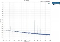
We were right that the heater stuff was also suspicious for that little 60Hz spike then. Can even be just the magnetic field of the heater's trafo if its near. That's a very clean noise floor for a tube build shown in your picture. Since it sounds nice too its a winner.
Salas,
I've finished building two SSHV2 with 420V output and 445V input. I've done following changes as you suggested in a previous post.
I replaced R10, R9 with 82K/2W resistor, and used large enough heatsink for Q5, Q4, and of course Q3. The load is less than 5ma per channel, so I adjusted R4 to have around 27ma through R5.
Everything looks ok, however I experience large voltage drifting from high to low. Under room temperature I have 435V output when firstly turned on then drop to 412V after 20min. I'd rather have lower voltage output when turned on then increase and stay stable after 30min
Maybe Q6 is the problem ? what would you suggest me to look at? Thanks in advance
Blow over Q6 area and if the voltage changes fast then that's the one plus the BJTs Vbe drifts. Its a very high I/V conversion ratio from 2.56mA to 420V so only 0.14mA IDSS thermal drift can give you that 23V delta.
Short the LED and see if the warm up drift behavior changes at all first.
There are several Watt burning on the nearby sinks and radiating heat. Adjust the CCS at 20mA to save on some heat.
Short the LED and see if the warm up drift behavior changes at all first.
There are several Watt burning on the nearby sinks and radiating heat. Adjust the CCS at 20mA to save on some heat.
Thanks Salas. I replaced the Q6 from another batch, it looks I get some improvement. The voltage goes to 428V then drop to 420 after 5 min then stay stable. With the LED being shorted it does not change drift behavior.
I also found that heatsinks for Q4, Q5 are a lot hotter than Q1
I'm wondering why the output voltage goes all the way up then drift down, not other way around?
I also found that heatsinks for Q4, Q5 are a lot hotter than Q1
I'm wondering why the output voltage goes all the way up then drift down, not other way around?
Could be the Vbe of the hot cascode BJTs which is Vds to the JFET (Q5's) changes with warm up. In so high a Vout they have more voltage across than in other builds so they dissipate more power. If you can boost the Q4 & Q5 sinking somehow it would possibly help. I have also wondered about replacing Q6 with several J201 JFETs in parallel up to enough Idss and better noise because they are 5nVrtHz FETS which also have far lower Gos and very low Idss individually, that makes them steadier as CCS units, but the whole thing could go chaotic when many (?) plus they are also NOS with lots of fakes floating around except in SMT or in expensive InterFet brand, there will be selection needed and a stamp size board to hold them either way. Big experimental trouble to take I would think for bettering (if successful) an 8V drop thermal drift in the scale of 428V after just using another K117 low noise Q6 sample with possibly different Vgs (off).
The only parts that are running very hot are Q4 and Q5 in my build because of much higher output voltage. So, this has caused the output voltage to drift lower as temperature goes up.
If I increase the value of R9, R10, would this reduce power consumption across Q4, Q5? I have replaced a pair of relatively lager heatsinks for Q4 and Q5, they only helped a little. I also tried to blow air on Q6, I don't see big change at the output.
If I increase the value of R9, R10, would this reduce power consumption across Q4, Q5? I have replaced a pair of relatively lager heatsinks for Q4 and Q5, they only helped a little. I also tried to blow air on Q6, I don't see big change at the output.
In the Eli Duttman and Co. "El Cheapo" amp (covered on a now-dead forum), there was discussion about the sensitivity of the DN2540 to static. My build of that amp (which sounds fabulous when it's working) has had recurring problems with the CCS in the long tail pair, though I don't know if the cause is the DN2540s. Others I know say it's a pretty robust transistor.
Salas I have a load of 150mA, it's possible to mod SSHV2 to support?
There are some much higher IDSS IXYS depletion mode parts to replace the DN2540s so to push the CCS limit high, like IXTP 08N50D2, but I don't know how stably they would react in practice. Dissipation and sinking would also change of course.
I use dozens of CCSs (both as anode load and current source) with DN2540 without any failure.... until its B+ "enough" low (practically up to 300V).
Over it I randomly (spikes?) lost a handful of FETs.
If voltage exceeds it, I use IXTP01N100D (1kV). Since then there is no death.
Over it I randomly (spikes?) lost a handful of FETs.
If voltage exceeds it, I use IXTP01N100D (1kV). Since then there is no death.
Stability
I have built a ccs/shunt based on the kandk version of the Salas simplistic HV.
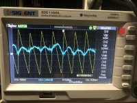
I am having some stability issues that I wish to reduce or eliminate. I am suspicious of my mains supply as well. But basically I gut this 4 to 8 mV ripple at 100hz. It also as I can best describe it undulates a little and has up to 20 mV jolts.
It seems to be fine in the linestage but I also have a 57db MC phono stage using this design.
At the moment I just have a 50uF cap coming off the rectifier and a 200 ohm resister feeding the ccs 290 volts for an output of 260 at 50mA. I tried increasing capacitance to the point where my ripple was 160mV , but no change in AC output, but maybe a little less stable.
I have built a ccs/shunt based on the kandk version of the Salas simplistic HV.
I am having some stability issues that I wish to reduce or eliminate. I am suspicious of my mains supply as well. But basically I gut this 4 to 8 mV ripple at 100hz. It also as I can best describe it undulates a little and has up to 20 mV jolts.
It seems to be fine in the linestage but I also have a 57db MC phono stage using this design.
At the moment I just have a 50uF cap coming off the rectifier and a 200 ohm resister feeding the ccs 290 volts for an output of 260 at 50mA. I tried increasing capacitance to the point where my ripple was 160mV , but no change in AC output, but maybe a little less stable.
Attachments
That K&K version I did not examine or authorize. I could vaguely say from a product photo its a hybrid of SSHV2 type CCS + SSHV1 shunt topology. Not sure about what parts are used also. So I am not adequate to really analyze.
From your scope's photo I may generally comment that the blue trace could be just ripple related noise and not an oscillation product per se but first make sure you measure without a standard long probe's ground lead but with a probe tip spring adapter. If things won't look any better, try measure the output with dummy load resistors of about same mA consumption as your preamp(s) to establish if the blue trace is a product of unstable interaction with the client circuits or intrinsic. Lets know those basic things first and we continue from there on.
P.S.
There is no Kelvin mode available and its a classic 2Wire output connection I would suppose. Is that right?
- Home
- Amplifiers
- Power Supplies
- Simplistic MosFET HV Shunt Regs