Theoretically yes but as physical constructions with double the area and more cables maybe more susceptible to buzzes? Zout should go down also. Another way is to use some IXYS type with more IDSS and VGS at least for Q1 so it allows more VDS for Q2 too. Maybe it could go to 150mA or more that way. Sinking always becomes a bigger problem when the mA at HV go up and up though.
SSHv2 working with negative voltage
Hello Mr. Salas, I will soon upload pictures of my phono preamplifier with the SSHV2, it works great.
I have a question for you, I have my preamp a grounted grid, which works with symmetric psu, and I want to install two SSHV2.
As SSHV2 would be to operate with negative voltage in this case -210V.
Very thankful
Hello, it will be nice to see your pics and to know more about how your phono sounds now.
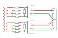
In low voltage applications we sometimes use separate secondary, bridges, and filter capacitors, to make a (+/-) from two positive regulators connected like batteries in series with a midpoint reference but I don't know if it could work with HV SSHV2 too without practical problems because I never tested it in such an HV config. Anyway here is how its done for anyone who would want to try and report. Shown in Kelvin output wiring mode.
In low voltage applications we sometimes use separate secondary, bridges, and filter capacitors, to make a (+/-) from two positive regulators connected like batteries in series with a midpoint reference but I don't know if it could work with HV SSHV2 too without practical problems because I never tested it in such an HV config. Anyway here is how its done for anyone who would want to try and report. Shown in Kelvin output wiring mode.
Attachments
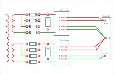
attach a power diode from + to 0 at the load and a second power diode from 0 to - at the load.
diode +ve goes to the more +ve terminal in both locations.
These diodes will turn on the filament of a Mains Bulb Tester if you get the wiring wrong. And more importantly limit the reverse voltage to <1Vdc
diode +ve goes to the more +ve terminal in both locations.
These diodes will turn on the filament of a Mains Bulb Tester if you get the wiring wrong. And more importantly limit the reverse voltage to <1Vdc
They must sustain the HV out as reverse voltage. Say its 300V out, use 600-1000V PIV for ample margin and any transient incident. So yes, they would be like the HV rectifier diodes spec or somewhat more relaxed.Do we use the same power diode as in the AC to DC circuit ??
Thank you Mr. Salas.Hello, it will be nice to see your pics and to know more about how your phono sounds now.
In low voltage applications we sometimes use separate secondary, bridges, and filter capacitors, to make a (+/-) from two positive regulators connected like batteries in series with a midpoint reference but I don't know if it could work with HV SSHV2 too without practical problems because I never tested it in such an HV config. Anyway here is how its done for anyone who would want to try and report. Shown in Kelvin output wiring mode.
Soon I will start up with my preamplifier.
Regarding my phono preamplifier is still under construction I still lack components.
I will comment your sound with your new psu
I attached you scheme.
Attachments
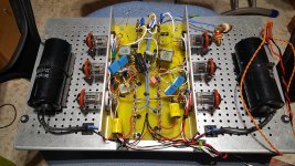
If so, I have a prototype, and with it is my test bench.You wrote the phono works great so I thought it's finished. Did you mean it went through some tests?
In the tests I am with the tubes 6S45P-E and 5751, I hope to have better sonic result with the 6S15P and ecc808
Here it is.
Any advice?
Attachments
The simulator says yes. It won't react bad to a 10uF 450V electrolytic Vref filter cap C2. For substituting the C1 0.33uF Zobel termination cap (works together with R6) the closest you will probably find at 450V is 1uF and you should also replace R6 with a shorting link because such a small electrolytic should have enough ESR of its own. Also expect a somewhat less defined sound vs using the original BOM's polypropelene parts of course. This can be synergistic or not to what your application is.
- Home
- Amplifiers
- Power Supplies
- Simplistic MosFET HV Shunt Regs