thank you very much .
You are welcome. Another thing I see is 285V and 255V B+ points in your preamp. You could adjust the series resistors following in those RC networks in your schematic for proper voltage drops to use one B+ value common for both points. Its simply about measuring DC drops on those resistors and applying Ohm's law to solve for current.
You are welcome. Another thing I see is 285V and 255V B+ points in your preamp. You could adjust the series resistors following in those RC networks in your schematic for proper voltage drops to use one B+ value common for both points. Its simply about measuring DC drops on those resistors and applying Ohm's law to solve for current.
Thanks again and I will follow your recommendation.
Another question and I know that is already very disputed.
Can I use this JFET, 2N4393-E3 instead of 2sk117gr, attached datasheet?
If yes what modification do you need?
Attachments
I don't think that you will chance on any lowest range 4393 5mA-7mA IDDS samples with -0.5V to -0.7V Vgs (off) that you need to replace the K117, but even if you will do, their en (nV noise voltage) is 10-15 times higher. No, not recommended. There is the in-production 2SK880GR surface mount direct equivalent that you can use a surface to through hole mini pcb adapter for it like those little platforms they sell on ebay.
I don't think that you will chance on any lowest range 4393 5mA-7mA IDDS samples with -0.5V to -0.7V Vgs (off) that you need to replace the K117, but even if you will do, their en (nV noise voltage) is 10-15 times higher. No, not recommended. There is the in-production 2SK880GR surface mount direct equivalent that you can use a surface to through hole mini pcb adapter for it like those little platforms they sell on ebay.
Thank you, Mr Salas, I will keep this in mind.
In this same forum I have found an Ebay provider in Germany that you recommend and the transistors are not fake.
thanks for your help
What test ot tests can we do to separate the real ones from the fakes ??
Visually there are some clues, technically is about confirming the datasheet by measuring IDSS & Vp for calculating gm unless you got a tracer and a surely original sample to compare full curves. See posts #4916,17,18 in the link: http://www.diyaudio.com/forums/powe...tic-mosfet-hv-shunt-regs-492.html#post4411651
Salas LV shunt regulator & CCS test is:
To only short F+ with F0 is enough
Can put 4.7k across each 68k, feed 30V input from lab supply and see if the output can adjust to 22V on 220R dummy. That would be a full LV test. If successful remove the 4.7k resistors and set the reg for its HV duty.
I guess the 220R dummy load is connected between S+ & S0, right?
Salas was a cold joint 68K resistor.
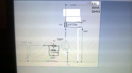
I have a question: I changed the 10K anode load resistor for 15k 600 ohms OPT to use as headphone the attached schematic, do you know how to calculate the new B+ value using the opt?
I have a question: I changed the 10K anode load resistor for 15k 600 ohms OPT to use as headphone the attached schematic, do you know how to calculate the new B+ value using the opt?
Attachments

Last edited:
- Home
- Amplifiers
- Power Supplies
- Simplistic MosFET HV Shunt Regs