I didn't blame anybody for anything. So - there is no need for sorry.Sorry Poty
")
would your answer be a yes then ??
...by-passing the big cap with a carefully calculated cap with the best suited porperty (material) can help with the speed??
This method is used in most radio-frequency designs and there is no problems to prove it.Definitely - yes!
But initially the question in the thread sounded differently. The goals were "energy" and "speed". If we plan to connect a big battery of capacitors ("energy"? I have questions here) together with thoroughly chosen by-passing film caps ("speed" - no questions, but low capacitance definitely), then what do we need the SSHV for? If we have "slow" "energy" battery then why is the battery better than getting the energy from the (equally slow) mains? If we have only tiny "fast" capacitance then what is the stored "energy" for?
Just adding one good technology to another is not enough to double their usefulness.
With our audio-frequency applications, how do you think we should calculate to get the best "energy" vs "speed" combinations of our capacitor choice under general terms ?? and with and without SSHV please ?
All my 10 & 26 line amps (and I do have a few of each) are all cap out-put......all CCS loaded now (by my design approach)........and I have tried to add SSHV 1........but personally I do not think that SSHV improves the performance of my amps under my situations.
I do by-pass all my electrolytic caps + my out-put caps.....only by try and errors.....by ear...
And would appreciate if you could share how I could calculate carefully to mach the "energy" and the "speed" caps please.
Cheers,
King
As you may have known from my previous posts I do not share "energy" and "speed" paradigms and incline more to the "noise" and PSRR tendency.
"General terms" is very misleading question, in that case the answer should be multi-hundred pages book which exists already for a long time.
And - yes - there are computer modelling practices (like LTSpice which was used by Salas) which helps to "play" with parameters.
And - second yes - I prefer do not load SSHV to capacitors.
As you may have known from my previous posts I do not share "energy" and "speed" paradigms and incline more to the "noise" and PSRR tendency.
"General terms" is very misleading question, in that case the answer should be multi-hundred pages book which exists already for a long time.
And - yes - there are computer modelling practices (like LTSpice which was used by Salas) which helps to "play" with parameters.
And - second yes - I prefer do not load SSHV to capacitors.
Poty....Poty.....please allow me.... to be a bit more specific, I do think that your answer is more in the "general terms" than my questions.....do you not think so ??
Yes, and I'm in doubt that anyone can answer your questions in more specific terms. It's not about concealment of something from my side. I'll try to explain:
There are many initial parameters influencing the resulting power supply design. To name a few: for circuit you want to power: PSRR, the current profile (static and dynamic), voltage requirements, need of regulation, useful frequency range, possible noise immunity (or otherwise - vulnerability), type of load (mostly reactive, mostly active) and so on; for power supply itself: bearable input properties (AC/DC, frequency, noise, internal impedance, load capacity...), the filtering/regulating capabilities, stability/damping, output impedance, static and dynamic load characteristics, output current and voltage, the kind of load, added noise (output noise) and so on.
Do you think that there is a way to give the solution to all this terms in one forum post?
SSHV2 has stable and very low output impedance and rather good stability margins (I envied Salas when I invented my own version of shunt regulator and it took me rather long time to achieve something comparable to his). Looking at the margins I could say that adding some capacitance at the output lower the safety distances to oscillation. The same is correct for inductive loads, but not in the eq amount. Looking at almost horizontal line of output impedance I could say that the equivalent in capacitor based systems is rather difficult to achieve (but not impossible). Does the SSHV suits all systems? No, it does not. Its simplicity justify some controversial things in it. It has some limitations in the output current and voltage. It may be used incorrectly with devastating consequencies. For some circuits it has to be adopted.
I can say that the counting for "slow-and-fast" capacitors design is not easier at all. You have to control the phase swings across the frequency, prevent big output impedance changes, allow the additional input power to charge such big capacitance... Yes, there are designs non-demanding to PS, which can be powered almost from any CRC-filter, but you should know your precious circuit before designing your power supply and use your circuit useful sides to simplify the power supply. Mechanically replacing one PS with another may not bring anything or worthen things.
I may only guess based on a similar design.
I'd consider +/-5% of mains and not more than 2V of p-p pulses after the first filter (the transformer and filter you should model, for example, in PSUD). I'd also taking into account that the SSHV2 will work with around min 10V across the CCS (difference between in and out) and around min 10mA in the shunt section. Yes, as pointed by Salas, there will be some degradation in the output impedance, but it will happen only while there is low mains voltage. So, min input-output voltage should be not less than 11V (I'd use 15V) and I'd take min shunt voltage =15mA. You use a schematic that stabilizes the current, it will help with the possible degradation.
So, max input voltage will be ((380+15)/0.95)*1.05=437V, CCS power: (437-380)*(20+15)=2W, shunt power: 380*0.015=5.7W.
I'd not count the faulty cases. If you really bother about such cases - there are simple circuits that can disconnect the regulator (like "electronic fuses").
Hi poty,
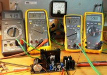
I tested your suggested settings, but choose somewhat lower values: mains fluctuation +/-3%. ((380+15)/0.97)*1.03=420V and a shunt current of 13mA. DC after filtering will be less then 1V p-p.
Here is what I get:
Meters from left to right:
Voltage IN (V)
Voltage Out (V)
Voltage TP (mV)
Temperature KSA1381, Q5 (°C)
I added more heatsinks to Q4 and Q5. Do you think 60°C is acceptable?
Regards,
Rovano
Attachments
60°C is OK. I'm sorry I definitely missed something. Why do you measure the temperature on Q4 and Q5? The counting was for Q1+Q2 (CCS) and for Q6 (shunt). Power dissipation for Q4 and Q5 mainly depends on the output voltage and differs not very much.I added more heatsinks to Q4 and Q5. Do you think 60°C is acceptable?
Is your R8 surely 1.8k? There should be about 4V VGS in Q3. If all is well then IQ4,Q5=VGS/1800=0.0022A (2.2mA). Dissipation Q4+Q5=381V*0.0022A=0.84W i.e. 0.84/2=0.42W for each one. Their sinks look rather big and the temperature still rather high. Check that those VGS and R8 values are correct.
Q1 should burn (419V-381V)*0.033A=1.254W in your picture. Can't be stone cold.
Q3 should burn 381V out * excessive shunt current available above load consumption. Expecting few W not cold.
Q1 should burn (419V-381V)*0.033A=1.254W in your picture. Can't be stone cold.
Q3 should burn 381V out * excessive shunt current available above load consumption. Expecting few W not cold.
Surely not 1,8k! I most certainly need a new pair of glasses! I am such a stupid cow, swapped R6 and R8! That explains a lot. Thanks Salas, for pointing this out.
Now I found that only 13mA for the regulator is not enough; not stable, too much voltage drift. When the current is set for the normal value (20 + 20mA), a total of 40mA, the heatsinks of Q1, Q4 and Q5 are about 35°C. Now the heatsink of Q3 is about 55°C.
Pfffff, this is a lot better! Thanks!
Now I found that only 13mA for the regulator is not enough; not stable, too much voltage drift. When the current is set for the normal value (20 + 20mA), a total of 40mA, the heatsinks of Q1, Q4 and Q5 are about 35°C. Now the heatsink of Q3 is about 55°C.
Pfffff, this is a lot better! Thanks!
SSHV2 for phono preamp
Hello friends.
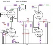
Soon I will receive my pcb for the SSHV2 construction, and I want to implement it in my phono preamplifier.
As SSHV2 has double output, I would like for my 6S15P, S + output, which are more delicate and F + for the 6N2P.
Attached image. Is the S + and f + jacks correct on the phono?
The total consumption of the phono is 18ma, it is necessary to make some modification in the SSHV2 ?.
Thank you in advance for your help.
Hello friends.
Soon I will receive my pcb for the SSHV2 construction, and I want to implement it in my phono preamplifier.
As SSHV2 has double output, I would like for my 6S15P, S + output, which are more delicate and F + for the 6N2P.
Attached image. Is the S + and f + jacks correct on the phono?
The total consumption of the phono is 18ma, it is necessary to make some modification in the SSHV2 ?.
Thank you in advance for your help.
Attachments
SSHV2 has not a double output, has a Kelvin output. S & F must meet at one same point. Use 38mA CCS setting in SSHV2. It has a trimmer and a test point for that. Read its pdf instructions file carefully.
Thank you very much Mr. Salas
* It is clear that it is simple output, and I will look at the pdf manual, which I did not have and read it.
Thanks again
Thank you very much Mr. Salas
* It is clear that it is simple output, and I will look at the pdf manual, which I did not have and read it.
Thanks again
By the way, I almost forgot.
Is the PSU for SSHV2 the same as SSHV?
By the way if you have space to install the SSHV2 near the preamp circuit so the cables can be not too long you can also use the classic two wire connection way. By shorting F+ with S+ and F0 with S0 using links at the regulator's output connector. Then each + and each 0 screw become a normal two wire terminal. B+/0. In that way and with thick enough cabling you have a simpler system against RFI or oscillations if you don't have an oscilloscope to know that the more complex Kelvin wiring mode is done screened well.
Yes, if you mean the raw DC PSU
thank you very much .
- Home
- Amplifiers
- Power Supplies
- Simplistic MosFET HV Shunt Regs