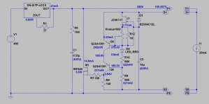
380V 20mA SSHV2
Each capacitor max. voltage at least 630V;
68k resistors will dissipates over 0.5W, so use 5W ones;
IRF840 needs large heatsink (about 3-4 K/W);
Don't use larger raw supply voltage than 400-420V, except CCS heatsink would be too small.
p.s. 2SA1381 will dissipate over 400mW, so use larger heatsinks (than small plate ones).
Attachments
Last edited:
Add a gate/source protection Zener.
What start up procedure is required?
Have a look at my schematic
Attachments
Salas,
What do you think Mundorf TubeCap 10uf 1000v for C2 on SSHV2? Is this capacitor suitable for the application?
https://www.banzaimusic.com/Mundorf-TubeCap-10uF-1000V.html
Thanks!
What do you think Mundorf TubeCap 10uf 1000v for C2 on SSHV2? Is this capacitor suitable for the application?
https://www.banzaimusic.com/Mundorf-TubeCap-10uF-1000V.html
Thanks!
Hi, Salas I remember you said in a post , for capacitive load, resistor in series must be used to isolate the capacitor otherwise the reg might oscillate. I'm just wondering how to calculator the value of the resistor? is there a minimun value? For example 100UF decoupling cap in circuit, can I add a small value resistor ( say 500R) or it's better just remove the cap?
In my opinion you should undertand first why do you need the capacitor? The regulator has already had low impedance. 4-wire connection helps to cover the distance between the regulator and a circuit it powers without adding some bad things. The regulator is stable. I do not know a necessity for a "decoupling".
The only sensible usage - multistage powering, when there is a series of RC filters which lowers the B+ voltage also. In the case I recommend to recount the stages to the full and unified voltage. You can use the counted RC-version certainly, but I do not think you'll have a benefit from it.
The only sensible usage - multistage powering, when there is a series of RC filters which lowers the B+ voltage also. In the case I recommend to recount the stages to the full and unified voltage. You can use the counted RC-version certainly, but I do not think you'll have a benefit from it.
Hi, Salas I remember you said in a post , for capacitive load, resistor in series must be used to isolate the capacitor otherwise the reg might oscillate. I'm just wondering how to calculator the value of the resistor? is there a minimun value? For example 100UF decoupling cap in circuit, can I add a small value resistor ( say 500R) or it's better just remove the cap?
For very small value & very low ESR local capacitor(s) across the load's rail if it results to oscillation you can put a small value resistor in series to it and effectively make RC. Like 0.33-1R. That could buffer it and stop odd effects with combining this type of regulator if any.
High values like 100uF most usually are electrolytic with some own ESR and don't interact the wrong way. When they are not absolutely necessary, but just additional local energy storage, the system could be tried without them also (faster system). Scoping on AC mode and sweeping from 1mS down to 50uS horizontal at 20mV vertical will surely show if the load's rail is still tame without sinusoidal style oscillatory additions.
Thanks all for help. The reason I ask is I'm not clear what to do when upgrading existing power supply that has capacitors in B+ power rail. Please see my drawing. (sorry for poor drawing)
In the drawing, when I connect the SSHV2 to it without removal of C3, the preamp goes oscillating straight away. Since the output impedance of SSHV2 is very low, there is no need to use C3 , if I understand Poty properly.
Then, what about R2 and C2 in some cases? If I was just to remove C2 and leave R2 there, will there be any negative impact in SQ? In this application, R2=1K, C2=100uF. I know, if R2 was big enough, say>10K for example, it'll be fine if C2 stays there.
Attachments
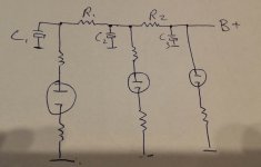
That C3 probably has very low HF impedance and upsets the specific reg. No bad result expected in tossing it though, Zo there is already very low as poty said.
Keep the R2-C2 R3-C1 cells. Those are useful progressive noise filtering and buffering RC cells between stages. If their resistors would have been left there alone then the signal following AC current drawn by the valves would have created an analogous voltage across those R. In other words signal modulation of the rail voltage. Nobody wants that. The C elements are there to hold local energy at low impedance very near to the points of consumption. The resistors create time delay of charge and make the noise filtering go deeper in frequency. They work together with the capacitors for that and as a dropper tool alone for bringing each stage's rail DC to what level the designer planned.
Keep the R2-C2 R3-C1 cells. Those are useful progressive noise filtering and buffering RC cells between stages. If their resistors would have been left there alone then the signal following AC current drawn by the valves would have created an analogous voltage across those R. In other words signal modulation of the rail voltage. Nobody wants that. The C elements are there to hold local energy at low impedance very near to the points of consumption. The resistors create time delay of charge and make the noise filtering go deeper in frequency. They work together with the capacitors for that and as a dropper tool alone for bringing each stage's rail DC to what level the designer planned.
- Home
- Amplifiers
- Power Supplies
- Simplistic MosFET HV Shunt Regs