It is unclear how did you tie the needed amount of inductance with the current. The load current dependence of the output voltage exists in any circuit with passive filtering.A choke input filter approaches 1.5Vac as the DC output when current falls.
The normally assumed output of DCV = 0.9Vac ONLY applies over a narrow range of load current.
That current range determines the required inductance. This is critical.
In most choke cores the less current - the more inductance you have.
There is a lot of ways to go. Some of them have already been mentioned. I'll add the possibility to use varistors and overcurrent protections such as crowbars, voltage detectors...OK. What would you advise then, Andrew? In case of a reg failure the first cap will see cap input voltage. I don't like that kind of situation.
I hope you are wrong.It appears you do not know how a choke input PSU works.
There are a few websites that explain the operation fully and give the required design formulae.
Go read.
")
I know there are several places where such claims exist, but mostly they are linking their assumptions to an early 19xx works where meaning of the "design formulae" was rather different.
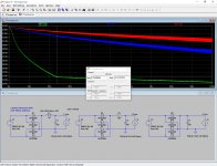
Just for fun I simulated three cases with the same "front end" (a 230V 0.27A transformer with 8% regulation and a Schottky bridge) and
- LC filter,
- RC filter with the same active resistance as the choke in the first case,
- C filter.
"Classic" view is that if you drop the load current to less than some value (determined by a formula) you'll "lose" the inductance properties and the filter will approach the pure capacitance model. Let's look at my simulation in the attachment. There are three graphs: red is pure capacitance filter, blue is the RC filter which imitates the choke "without inductance", green is LC filter in question. The 0s point is 0mA of load, the 100s point is 100ma load. The function of the current is linear between the points. To achieve some steady state I allowed the models to work for 20 sec before the 0s point. We can see that there is a knee in the LC graph, but the whole continuity of the graph shows that there is no losses of inductance properties. In reality the inductance of choke will increase with decreasing current smoothing the transition ever more.
By the way - if you want to determine a minimal load which allow you a safe voltage point you can look at the green graph. For example if you have a capacitors rated 250V (-10% safety margin=225V) you should not have less than around 20.5mA of load current which gives you 225/20.5=11k resistor with more than 5W of dissipation.
Attachments
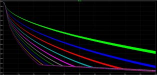
Unfortunately I could not understand what you mean saying "effective", but the second part is easy (see in the attachment).Could you do simulations trying to find the smallest value choke that could be of effective??
Or just to see what smaller chokes could do under the same situation, please??
But you can easily make this simulations yourself: the program is free and (while not so user-friendly) easy in use. PM me if you have questions about it.
P.S. Sorry, some comments: there are 10 graphs representing inductances from 1H (top, green) to 10H (bottom, dark magenta) with step of 1H (so the blue line is 2H, red line is 3H and so on). In reality there will be some differences, like different active resistance of chokes, but the changes will not be big.
Attachments
Last edited:
Can you see your problem?
The increase in voltage from 217Vdc to 348Vdc is what could break your capacitors if you don't design for worst case voltage conditions.
And when mains voltage is at 106%, it gets worse !
Can you see your problem?
- this conditions exist with any type of filter,A choke input filter approaches 1.5Vac as the DC output when current falls.
- the range is definitely not narrow,The normally assumed output of DCV = 0.9Vac ONLY applies over a narrow range of load current.
- the 0.9Vac "assumption" is here for school beginners,
- in my simulations you can see that there is no critical points, there is a knee dividing different stages of effectiveness, which may or may not be taking into consideration,That current range determines the required inductance. This is critical.
- overvoltage and overcurrent protection must be taking into account, but you cannot design a choke input filter suitable for all possible current situation just by choosing the right inductance, one must add other meanings of protecting from the bad things.
In many sources I saw a recommendation to take into account current swings of the load (relating to the choke input - to choose the "right" inductance), but this is plainly wrong, because all current fluctuations should be "served" by the capacitors on the output. On the other hand, if there is the possibility for long DC-like changes (while I do not know how it may be seen in audio) - then you must protect not only filter elements, but also circuit (load) itself by some sort of regulation, such as SSHV.
Last edited:
There is no facts in your claims. Since none of your words proven to be true I do not want to litter the thread further.It still seems to me that you don't understand how a choke input PSU works.
I thought when you developed and posted those results of Vout in your model you were getting there. The model is good work.
But it seems the understanding is not there.
Last edited:
Unfortunately I could not understand what you mean saying "effective", but the second part is easy (see in the attachment).
But you can easily make this simulations yourself: the program is free and (while not so user-friendly) easy in use. PM me if you have questions about it.
P.S. Sorry, some comments: there are 10 graphs representing inductances from 1H (top, green) to 10H (bottom, dark magenta) with step of 1H (so the blue line is 2H, red line is 3H and so on). In reality there will be some differences, like different active resistance of chokes, but the changes will not be big.
Thankyou for doing the simulation.
Do you think a 3H choke would be effective enough for a B+ PSU, with a CCS loading the tube, and with or without a SSHV??
What about the chokes for the filament supply?? (please let me squeeze this one in while talking about chokes here....)
Both questions worth a separate thread. I believe an example of building a power supply will benefit everyone.Do you think a 3H choke would be effective enough for a B+ PSU, with a CCS loading the tube, and with or without a SSHV??
What about the chokes for the filament supply?? (please let me squeeze this one in while talking about chokes here....)
In short for B+:
- CCS loading enables pretty stable current drawing from the power supply. For 3H choke the current should not be below 85-90mA if you want to use "continuous current" approach (it seems the only way for AndrewT to engineering the choke input power supply), otherwise you can use any current you want. You should think about power on sequence to save your circuit from high voltage.
- CCS loading usually brings good PSRR, but you should check the amplitude of residual pulses after your filter. There should be also considerations of damping the low-frequency oscillations in the LC circuit.
- the addition of SSHV power-supply-wise does not change anything (taking into account the CCS loading), but improves the predictability of the output voltages, smoothes ripples and filters some wideband noise.
In short for heaters:
- heaters can be seen as CCS so all considerations for B+ preserve here. Due to high currents you can use low-inductance chokes if they are enough for smoothing ripples.
The alternative is to design for worst case voltage of ~368Vdc instead of the choke input giving ~217Vdc, after everything has stabiklised and one assumes the load is usually present...............- CCS loading enables pretty stable current drawing from the power supply. For 3H choke the current should not be below 85-90mA if you want to use "continuous current" approach (it seems the only way for AndrewT to engineering the choke input power supply), otherwise you can use any current you want. ...............
"CCS loading enables pretty stable current drawing from the power supply"The alternative is to design for worst case voltage of ~368Vdc instead of the choke input giving ~217Vdc, after everything has stabilised
The graphs show that there are many different voltages between the two voltage values you mentioned. You should design for your real situation.
Also:
"You should think about power on sequence to save your circuit from high voltage."
It's right for both scenarios. No choke can prevent the voltage rising without any load as you can see on the simulations.and one assumes the load is usually present.
Many things depend on the actual circuit (load). There are mainly three points of interest: 1. Properties for the load. 2. Properties for the transformer and other circuits (not the load). 3. Properties for the SSHV if used.Just to keep my question within the range of this threat, I would like to ask: when using SSHV, what practical difference if I use choke loaded PSU compared to say cap loaded, or other forms of PSU?? and then any other differences when I take the SSHV off??
"difference" above can read advantage..... or similar.....
For the load SSHV provide great stability (regulation) (allows to use parts near their limit), low ripple (allows circuits with low PSRR) and low output impedance (no coloration of the last capacitors and better low-frequency response). It's all positive features which could be easily lost if SSHV is omitted. A side positive effect is small requirements for filtering (ripple could be high) before SSHV. Adding SSHV is not free: you have to have additional voltage and current. Relating to the filtering components before SSHV - as soon as you have all requirements for the SSHV input - there is very small difference.
Choke loaded (thank you for the right term, I have difficulty to use English terms) PSU+"continuous current" approach is good for transformer and other power supplies connected to the transformer or to the same power cord circuits (sorry for long description) due to much lower "switching noise". This property is good for the load too (if we don't use SSHV), even if the load has good PSRR (like CCS loaded anode), because the noise is wideband and a CCS usually has limited bandwidth for decent response. Negative sides are EMI from the choke(-s) and relatively low output voltage (which brings back our discussion about building a proper protection or use high voltage parts). The design of LC filtering also raises question about damping self-resonant oscillations.
Caps loaded PSU (or better - CRC filtering) is easier, smaller, could achieve higher output voltages (less margins for parts' voltage) and necessary ripple values, but you should take into account the switching noise, the design of the transformer becomes more complicated, there are also some limitations for rectifier parts (allowable pulse current) especially in tube world.
I may name only a few features, but I think they are main considerations in choosing a schematic for a circuit.
Last edited:
SSHV2 question for 6V6 preamp
Greetings! ( long)
Any suggestions or advice would be most helpful as I'm stuck and not sure if I'm on the right path.
I'm slowly building the SALAS 6V6 preamp based on this schematic in post 81
http://www.diyaudio.com/forums/tubes-valves/102352-6v6-line-preamp-9.html
I've changed a few parameters in the PSU to suit what I already have. The modified PSU is as follows:
Hammond 372JX (300-0-300 CT, 250 mA DC) > GZ34 > 5 Ohm (5W) > 4.7uF > 10H choke (Hammond 193M 300mA) > then splits into two rails, with the following per channel > 310uF (per channel) > SSHV2 (per channel) & there is where I get stuck.
Each channel has 370 VDC for each SSHV2. I have a 9.5K 20W load for each SSVH2. The LED's light up for each SSHV2 and I can set 40mA for each as desired. One board works as desired and I can set it to 340 VDC . The other SSHV2 only goes up to 299 and then maxes out at 310 VDC (no matter how many turns for R11) after a half hour and stays there.
I thought it might be the NJFET Q6 (K117GROK) and changed it out with a spare that came with the kit. But now the board only reads 200 VDC and I know I messed up the board trying to change it out and have since ordered another SSHV2 board.
Did I ask too much from the mains power transformer and it just couldn''t keep up? Do you have to de-rate the Hammond transformers & chokes (by how much?)? Or should I have inspected the SSHV2 more closely?
Any help would be appreciated.
Cheers
Frank M
Looks like its about relatively low IDSS in your JFETs for your Vout goal. Avoid the new JFET use the previous or some other and change the two 68K resistors to 82K ones so they can push to more output voltage with less Vref current. Also use 15K 20W dummy for your tests which represents one channel 6V6 preamp load much better. So you can evaluate dissipation and sinking on the output mosfet more realistically.
- Home
- Amplifiers
- Power Supplies
- Simplistic MosFET HV Shunt Regs