I read 104pF between C-B pins (-C +B probing) on Fairchild KSA1381 original when out of circuit is a check point. I saw 2SA1381 available on first look in reichelt.de maybe you can find it in Italian reputable stockists too, but if you get the classic MJE350 in some local store its good enough to prove a fault. Last suspicions before trying BJT: Is the input voltage holding well higher than 80V when testing? Is the Zener D3 OK, is the pcb clean from flux residue? Do you have a picture of the build including what you connect to it so maybe we can spot something weird?At the time being I have no spare.
I will try to find locally but not sure to succeed.
Otherwise there is internet but you are speaking of faking semi. Do you have any suggestion where to get the right parts?
Hello to everybody.
Need someone help to help me solve the issue I am facing.
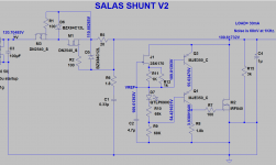
SSHV2 kit on breadboard 3kohm load with CCS set to 50mA.
Raw DC 120V 30ma needed on load.
The trouble is that I can change the CCS set but I am not able to go over 77-78V on the output (when I turn R11 voltage does not change). I made some checks according to the guidelines I found on this thread:
please see my image for see all V at pin off transistor
thanks
Attachments
Last edited:
The SSHV2 can work down to only 10V drop across it. It will also draw 20mA more current.
Sound is usually different between shunt and series PSU. That has to do a lot with how the client circuit reacts to the PSU and the design of each specific PSU though. The one you show is fairly busy has LM317 too. You could only know how SSHV2 fairs against it in a specific task by trying it.
Sound is usually different between shunt and series PSU. That has to do a lot with how the client circuit reacts to the PSU and the design of each specific PSU though. The one you show is fairly busy has LM317 too. You could only know how SSHV2 fairs against it in a specific task by trying it.
- the output impedance stability across all audio frequencies;Anyone able to tell me what area will be improved if the replacing the series regulator (attached) as shown with SSHV2?
- wider isolation from the mains AC (not only 50(60)Hz, but other wideband junks also);
- less noise;
- much easier choice of the filtering elements, particularly - capacitors and much faster power supply recovery after peak consumptions.
It depends on the actual circuit to power (completely agree with Salas in the area).Does the Salas drop more voltage and draw more current than this series type regulator?
IMHO, the answer is the same as in the previous question.What about sound?
Last edited:
Sorry if this covers old ground but I have managed to damage my SSHV2. I followed the advice(great info from Salas on I think page 448 onwards of this thread) and found some faults. What I found was that D2 was blown and Q5 a short between E and B. I will change these later. There may be other faults.
My questions are:
1. What causes the failures, can accidental short-circuit cause the problem? I am trying to work out if the issue is the SSHV2 itself or the linestage it is feeding (250V, 50mA).
2. Is there a definitive guide to fault finding for this regulator, its very hard to wade through 507 pages.
Cheers
Ian
A failure in Q5 dragged things along I would suppose. Was it working as a system with the linestage for some time with no issues? Was it fused? An accidental short can make Q1 dissipate a lot, it will hold for a while, but a live release from the short can bring overvoltage to caps and the semis. I can't speculate better on what was the trigger mechanism before there is a more detailed account of the event.
The link from post #1 to that troubleshooting exchange you followed is the best.
You should check all other semis including Zeners doing the same steps.
The link from post #1 to that troubleshooting exchange you followed is the best.
You should check all other semis including Zeners doing the same steps.
Hi Salas,
The regulator had been working for some time. However, I was fiddling with yet another modification to the preamp when the regulator failed and it is entirely possible that I shorted it out!! I am normally very careful but got caught out.
I will probably change all the zeners as they are so cheap.
In the CCS Q1 only measures about 0.7V VGS which seems a bit low. Q2 measures about 2V. However, the CCS does seem to be able to set the current and this current is approximately the same as the total current being drawn by the CCS (As described in your test). Do you think I should change Q1 anyway?
Cheers
Ian
Q2 is not a BJT, so Vds could be easily less than Vgs (see for example the Output Characteristics and the Saturation Characteristics of the DN2540 in the datasheet). Why the Vgs of Q2 is too big - is another question.Because its a FET cascode and Q1 Vgs is Q2's VDS effectively so it can't be less than Q2's Vgs (2V he measured). It is (-) Vgs indeed in N type semis but we just usually refer to its value only.
For Q2 to function properly as CCS i.e. past its ohmic region, VDS should be at least equal to |Vgs| and ideally >|2Vgs|
Q1 is shielding it in common gate mode providing its VGS(OFF) as VDS for Q2 and the DN2540 datasheet says min VGS(OFF) -1.5V so some Q1 with -0.7V is suspicious anyway
Q1 is shielding it in common gate mode providing its VGS(OFF) as VDS for Q2 and the DN2540 datasheet says min VGS(OFF) -1.5V so some Q1 with -0.7V is suspicious anyway
It greatly depends on the desired current and not so straightforward. For example, for the Id=20mA, Vgs=-1V and the saturation begins from around Vds>0,7V.For Q2 to function properly as CCS i.e. past its ohmic region, VDS should be at least equal to |Vgs| and ideally >|2Vgs|
Not at all. Vgs(OFF) defines the minimal voltage (taking into account a sign) @ some defined Vds (in our case =25V) when the current through the drain drops to a defined value (in our case = 10µA). -0.7V is greater thanQ1 is shielding it in common gate mode providing its VGS(OFF) as VDS for Q2 and the DN2540 datasheet says min VGS(OFF) -1.5V so some Q1 with -0.7V is suspicious anyway
-1.5V, then Q1 can conduct. It is Vgs=-2V for Q2 (so - below Vgs(OFF)) that worried me more. At that voltage Q2 should not conduct at all, but Ian said that it worked and even regulating current! For me the measurements are suspicious, not the -0.7V Vgs for Q1.
Dear Salas,
I am having trouble to understand the total power consumption of the circuit attached, and I might have underestimate the needs in ordering the transformer.
I set R1 to 47 ohm and I measure 2.3V across it.
I have 250V AC in input.
R3 is 56K.
The load is 30mA.
Output 270V.
Everything wonderful, but why am I pulling 118mA from the primary at 230V ?
Should it be like this or I have some oscillation somewhere ?
I had estimated a need of 70mA and now I am way short.
The cabled to the load are 0.5 cm.
Thanks,
Davide
Attachments
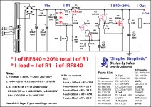
Then, the part to the right of R1 is taking 49mA. IncludingI set R1 to 47 ohm and I measure 2.3V across it.
Then:The load is 30mA.
The current is approximately 5-6mA.I have 250V AC in input.
R3 is 56K.
It's all that Salas' circuit consume. The rest is the losses in the rectifying and filtering. I'd lower the first capacitor considerably or add some resistance before the bridge.
How many R3 have you used?
R3=56k with 330Vdc will pull 5.9mA each. (check the power dissipation of this resistor? Do you need to use series connected resistors?)
R1=47r with 2.3Vdc will pull 49mA
Leakage through C4 & C5 should be <<1mAdc. Did you reform them (slowly) before assembly?
Total draw will be ~5.9xN + 49 + 0.1 mA
If N = 1 then total secondary current is 54mA and your secondary current rating should be >>108mAac
I would select >=200mAac
If N=3, then >=260mAac
Note, that output current draw does not enter any of the calculation.
That is the way CCS fed Shunt Regulators work.
Last edited:
- Home
- Amplifiers
- Power Supplies
- Simplistic MosFET HV Shunt Regs