Most probably fakes. GR types should span their spec 2.6-6.5mA fairly well in a batch of 50pcs.Thanks for your help. yes, Jfets are from ebay, but I did the PCB.
P.S. 5mA per channel you wrote. Is it just bias or includes the top demand when max signal is run? Allow for top demand. If its one reg for two channels, set 30mA CCS as minimum (20mA base + 10mA load). 40mA would be more secure. Always check the drop on your CRC pre-filter not to become too much for a given R there when increasing CCS. 20V rawDC - VoutReg is enough margin.
P.S. 5mA per channel you wrote. Is it just bias or includes the top demand when max signal is run? Allow for top demand. If its one reg for two channels, set 30mA CCS as minimum (20mA base + 10mA load). 40mA would be more secure. Always check the drop on your CRC pre-filter not to become too much for a given R there when increasing CCS. 20V rawDC - VoutReg is enough margin.
Thanks for your suggestions. 5ma is the bias per channel. How many ma is the max margin I should consider? I will use 2 regs for the preamp.
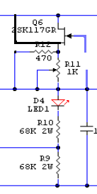
I found some 2SK117 BL and tested all Idss are around 14ma. They work fine without changing the 68K resistor to 75K as you suggested. But these Jfets act differently. When turned the reg on, the output goes to max around 300V, then drifts downward as temperature arises. But when ebay 2SK117GR were used, outout drifts upwards as temperature arises.
What do you think I should use, the Ebay Jfets with 75K resistor or 117BL is just fine to use ?
Set the regs at 30mA CCS each so they work a little. The demands are low in your circuits.
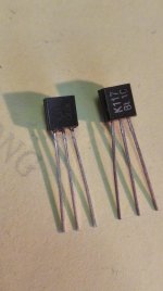
When a JFET is heated it should source more current thus causing more drop to the resistors, i.e. more Vout. But the BL could be behaving otherwise due to incompatible Vgs (off) in this circuit. Can you post a macro shot of your BL and GR?
When a JFET is heated it should source more current thus causing more drop to the resistors, i.e. more Vout. But the BL could be behaving otherwise due to incompatible Vgs (off) in this circuit. Can you post a macro shot of your BL and GR?
Set the regs at 30mA CCS each so they work a little. The demands are low in your circuits.
When a JFET is heated it should source more current thus causing more drop to the resistors, i.e. more Vout. But the BL could be behaving otherwise due to incompatible Vgs (off) in this circuit. Can you post a macro shot of your BL and GR?
Here is the Jfets. The right one is from a local verdor
Attachments
I am curious about two things before using the SSHV2.
1. How critical is an undamped Q factor of a power supply LC filter after the (tube) rectifier and before the regulator? Because the regulator's consumption should be pretty constant. The resonant frequency is ~2Hz
2. For a tube in class A single ended mode, the tube will be biased in the 25mA-30mA, but will swing up to 45-50mA. At how much current should be the regulator biased?
Thanks.
1. Never hooked it to a woofer pumping if used alone passive filter DC feed for Vin. But you have a good chance that the CCS will isolate that thing since its doing constant current draw down to DC.I am curious about two things before using the SSHV2.
1. How critical is an undamped Q factor of a power supply LC filter after the (tube) rectifier and before the regulator? Because the regulator's consumption should be pretty constant. The resonant frequency is ~2Hz
2. For a tube in class A single ended mode, the tube will be biased in the 25mA-30mA, but will swing up to 45-50mA. At how much current should be the regulator biased?
Thanks.
2. Set 70mA CCS in the regulator
Both fake.
Finally, I've got some real Jfet and now the reg is working with a lot less drifting.
But one thing I don't understand. Once I replace the Jfets, Q3 IRF840 on both channels blown up for unknown reason (very low resisitance between Source and Gate ). I just replaced the Q3 for both channels and they all worked fine after all. The reg worked before with fake 2SK117-BL.
Will that help if I put a 12V ptotection Zener diode between Source and Gate on Q3?
yes, it must be the cap discharges because I did not wait long enough from power off to start reworking. Anyway, it's working now and one thing I have to say, with the real Jfet nstalled, the preamp sounds much better than before and I can feel noticeable lower noise level. thanks Salas
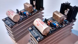
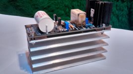
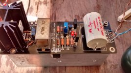
Today two HV boards were born! Dedicated for my tube SET amp's IT coupled driver stage, they are set to 200V 65mA. Built with Dale, Mundorf and RIFA parts.
I want to thank Salas again for this great project, enthusiasm and help, and also to Teabag for these beautiful boards!
Enjoy some photos!
I want to thank Salas again for this great project, enthusiasm and help, and also to Teabag for these beautiful boards!
Enjoy some photos!
Attachments
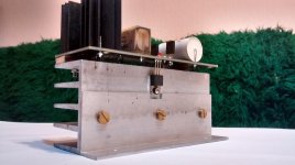
Beautiful photos, and good looking joints. The thick mounting spacers won't allow the parts to slowly cook on those bottom sinks. All things taken care of. Congratulations.
Did you try them on the actual driver stages rails by now?
Thanks. The big sink is a bit oversized, but I got space in my amp build.
I've tried them only with a dummy load. Connecting them to the amp is to come. I hope nothing will oscillate
Jameshillj, thank you for the info, I'll have this in mind.
Today I wired the regulator to the tube driver stage. My PSU sagged more than simulated with PSUD, so I had to reconfigure the regulator to 190V. The feeding voltage is 210V. It's okay right now. I didn't put the scope to test yet, I'd like to do this after final assembly.
The tube is biased at -2Vg /24mA. It will swing to 45mA max. 65mA of shunt current should be enough for headroom, right?
The tube is biased at -2Vg /24mA. It will swing to 45mA max. 65mA of shunt current should be enough for headroom, right?
- Home
- Amplifiers
- Power Supplies
- Simplistic MosFET HV Shunt Regs