When having say 300V and someone has a hot sink already because of limited space in an assembly for just the 20mA allowance he better not let it open burn say another 50mA that was allocated to the load for long. The shunt has the same functional blocks as the LV ones. Its a matter of space and thermal economy. If they like they can use sinking for full dissipation in long term open circuit event. Above all don't stress circuitry or play hard testing if not sure and experienced when on HV is my angle to the many builders especially those not in experience with HV regs. Messing with HV to a minimum keeps us safer.
But I am talking about designing for survivability.When having say 300V and someone has a hot sink already because of limited space in an assembly for just the 20mA allowance he better not let it open burn say another 50mA that was allocated to the load for long.
Hot during normal operation could be 60°C.
If the output did become open circuit the amplifier would turn off in some way indicating a fault.
During the time it takes to think about the problem (and maybe power down) the sink is increasing in temperature aiming for the worst case. That could be 100°C, more or less. What I would want is no damage during this episode.
What most builders would not want is for the Shunt to damage it's self during this mishap.
Hi guys,
Pls point me where i could find a pcb or a kit if they are available.. Thanks very much
http://www.diyaudio.com/forums/group-buys/206033-gb-salas-sshv2-regulator.html
But I am talking about designing for survivability.
There is IRF840 designed in which is a 1C/W RthJC 125W @ 25C device. TJ=125C. Gives plenty of room for survivability to be mainly a matter of its sinking and ambient temp. Can't recommend a certain sink for all because of the wide voltage and mA range in this variable HV regulator. Also the extra current allowance is down to user's content bar the 20mA baseline, makes it an even wider sinking choice. I would give an idea with a broad example. If burning about 6W normally and there is about 40C ambient not that near to tubes or in box, a 2C/W sink will pass for 15W when no load is connected. Better not for too long because it will up the ambient also if in a box.
I expect every Member /Builder to eventually have learned the skills of sizing a heatsink for them selves.
As you already know I do not suffer lazy Members gladly.
I expect them to do the Homework for their Project. If their Project is not important enough to deserve the learning effort, then in my book they are in the wrong hobby. DIY really does mean do it yourself.
Not:
"I want to build a modified version this week, give me the recipe, btw, I will change my demands for Forum support and ask for a new recipe next week/month."
Do I need a transformer?
I need 300vdc Vout from my Salas HV Reg.
Just out of interest (as I have 230vac mains), why do I need an expensive transformer to get the desired dc input volts to the reg, as my mains 230vac rectified will be approximately 320vdc which is the specified 20vdc higher than my Vout target.
So, do I need a transformer?
Thanks
Ah, OK, been doing a bit of reading on safety aspects of using a transformer - thanks.
I've have got an isolating transformer that I use for my power tools so I might use that to try-out the reg.
I've have got an isolating transformer that I use for my power tools so I might use that to try-out the reg.
one word... ISOLATION!
I need 300vdc Vout from my Salas HV Reg.
Just out of interest (as I have 230vac mains), why do I need an expensive transformer to get the desired dc input volts to the reg, as my mains 230vac rectified will be approximately 320vdc which is the specified 20vdc higher than my Vout target.
So, do I need a transformer?
Thanks
Balancing power/conditioner
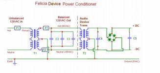
While looking at building a PSU, I came across a design by Occam on Audiocircle: the Felicia balancing powerconditioner.
Another member produced this alternate circuit (schematic below) that I thought might work with either the SSHV and SSLV reg's. (Felicia Balancing PowerConditioner Constructor's Thread).
More on the original cct here:FELICIA - A DIY Balanced Power Conditioner
Salas, do you think this might be a worthwhile improvement to either of the reg's or there would be no significant advantage using the balancing power/conditioner.?
Attachments
While looking at building a PSU, I came across a design by Occam on Audiocircle: the Felicia balancing powerconditioner.
Another member produced this alternate circuit (schematic below) that I thought might work with either the SSHV and SSLV reg's. (Felicia Balancing PowerConditioner Constructor's Thread).
More on the original cct here:FELICIA - A DIY Balanced Power Conditioner
Salas, do you think this might be a worthwhile improvement to either of the reg's or there would be no significant advantage using the balancing power/conditioner.?
What is seen in the attached photo is an isolation transformer with balanced output.
I have 4 such isolation transformers in my audio setup (1 for the Power Amp, 1 for the pre-amp and phono stage, 1 for the CD Player and 1 for the Audio/Video Receiver and the Universal Player [both have switching PSU]).
Isolation Transformers, especially those with balanced output, are great for improving the sound of the setup.
Transformer
Hi! Does anybody know if I can use 2 12V transformers (secondaries together) so I can get the same voltage from the outlet? If OK how to calculate the current specification for the secondaries?
Thanks and regards,
Adriano
Ah, OK, been doing a bit of reading on safety aspects of using a transformer - thanks.
I've have got an isolating transformer that I use for my power tools so I might use that to try-out the reg.
Hi! Does anybody know if I can use 2 12V transformers (secondaries together) so I can get the same voltage from the outlet? If OK how to calculate the current specification for the secondaries?
Thanks and regards,
Adriano
Last edited:
What to feed the SALAS regulator?
Excuse me if this has been discussed one hundred times but I have not found it addressed.
Is there a general recommendation for what precedes the SALAS?
I plan on using a CLC filter after a tube rectifier. I figure this is what should be used (the CLC part) but would welcome recommendations.
Has anyone used the LUNDAHL chokes in the "improved common mode rejection" connection? Is it worth the trouble?
Also, did I read that using a choke after the regulator is not good. Would someone assure me this is correct?
Excuse this if it has been repeated (ad nauseum) - but with TEABAG's group buy I suspect there are a few of us who have not kept up with the thread since the beginning who would like to know.
Thanks to Mr. Salas for his generosity and TEABAG for his making this easy for folks like me! And thanks to any who offer answers.
There is no certain passive pre-filter guide because everybody has his budget and his preference and the reg will not object different stuff like choke input, RC, CRC, CLC, tube rectifier, solid state bridge. The only guide lines are decouple with a small value capacitor across the reg's input if there is more than short cabling coming in from last filter output cap, and don't use extra filtering inductance on its output. It will certainly destroy its output characteristics and can make it oscillate even.
Hi! Does anybody know if I can use 2 12V transformers (secondaries together) so I can get the same voltage from the outlet? If OK how to calculate the current specification for the secondaries?
Thanks and regards,
Adriano
120VAC secondaries in series you mean? That will give you 240VAC at half the current.
Follow up to feeding the SALAS
Mr. Salas,
Thanks for your advice.
I guess I should have made this clearer: is there anything one should not do?
I have read of some regulators that want an almost direct connection to the rectifier and then there are those that benefit from additional filtering before the final scrubbing. An example of the former would be the BELLESON.
If expense was not a consideration how far would you go with the pre-filter?
Where would you guess one reaches the point of diminishing returns?
(hope this is not perceived as argumentative!)
Thanks again,
120VAC secondaries in series you mean? That will give you 240VAC at half the current.
Hi Salas, sorry it wasn't clear... Let me try to explain graphically:
(home AC outlet 120V)=======(1st Trafo pri120V/sec220V)==========(2nd Trafo pri120+120V/sec12V)============(Ac output 240V)
120V ==================== PRI // SEC ===================== SEC // PRI ============================ 240V to rectifier/regulator
My concern (if it is possible) is to specify the trafo secondary current, so I can get enough current at the output....
Regards
Last edited:
- Home
- Amplifiers
- Power Supplies
- Simplistic MosFET HV Shunt Regs